Optical connector and connection structure of optical fibers

a technology of optical fibers and connectors, applied in the field of optical connectors, can solve the problems of increasing the loss of the end face profile of optical fibers can seriously affect the connection characteristics, and the method of polishing the end face of optical fibers or the ferrules is not suitable for connecting optical fibers, so as to facilitate the connection of optical fibers, reduce the number of changes, and the effect of easy removal

Inactive Publication Date: 2007-08-23
HITACHI METALS LTD
View PDF4 Cites 24 Cited by
  • Summary
  • Abstract
  • Description
  • Claims
  • Application Information

AI Technical Summary

Benefits of technology

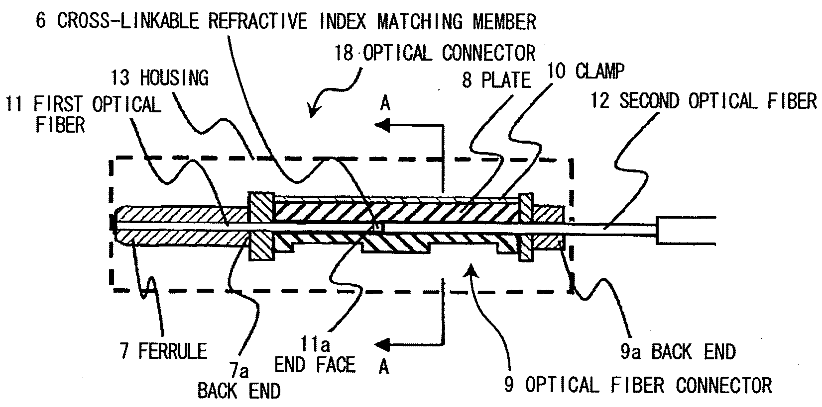
[0043]According to the invention, an optical connector that can easily connect optical fibers (in particular, holey fibers) in a setting site thereof, after the optical fibers are cut, in an original state of the cutting without a requirement of polishing the end faces of the optical fibers, can be provided.
[0044]Further, an optical connector that less subjects to a change with time (due to a temperature dependency), can be easily attached and removed repeatedly, and comprises a high stability of an optical transmission characteristic and a good connection characteristic, can be provided.
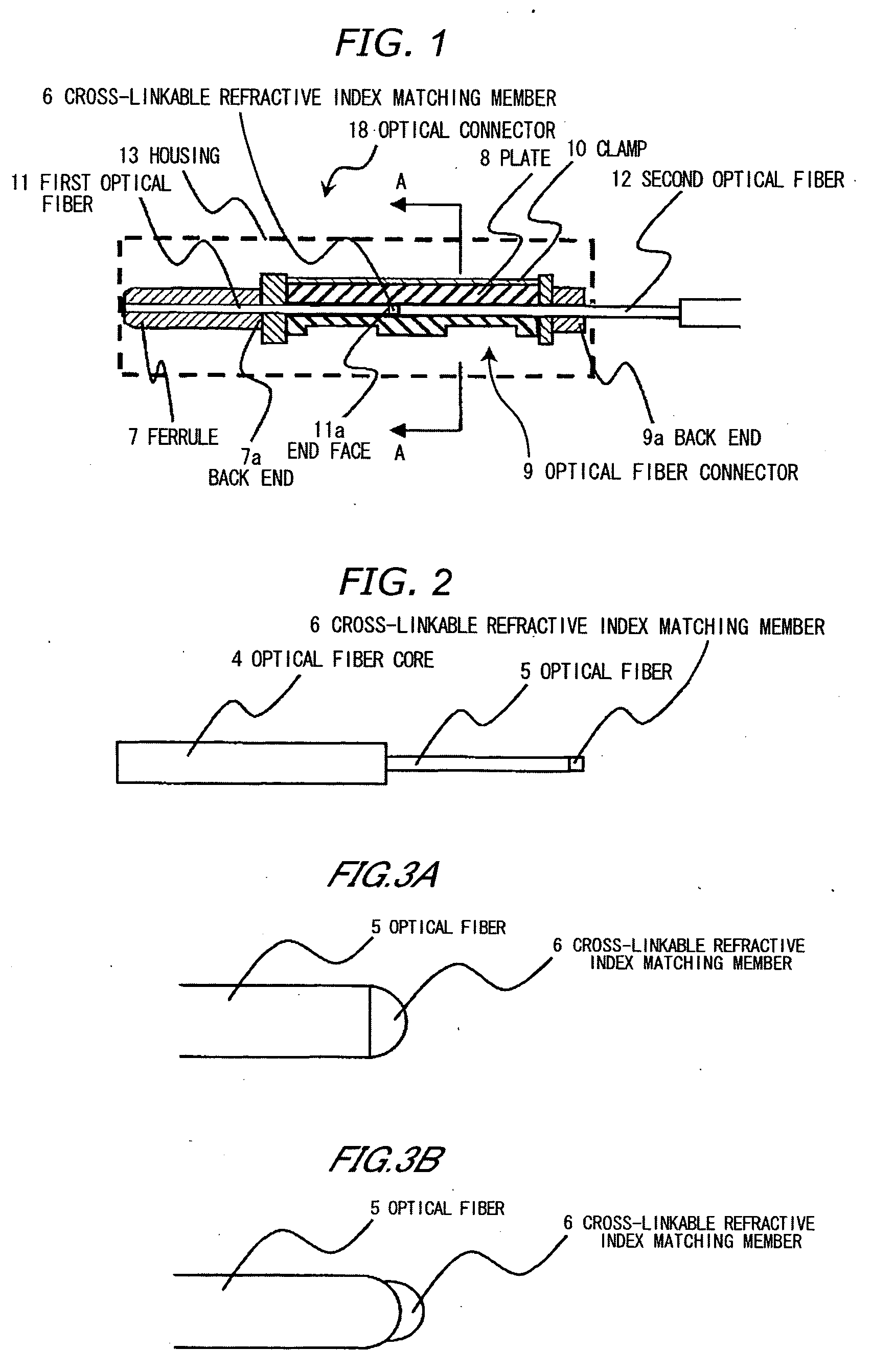
[0045]Further, the optical connector according to the invention comprises a structure that a face shape of the cross-linkable refractive index matching member contacting the end face of the second optical fiber to be inserted to the optical fiber connector from the side of the back end thereof is formed to a spherical shape, so that the optical connector can achieve the following advantages (1) and (2). That is, the end faces of the optical fibers can be brought closer to each other in comparison with a case that a face of the cross-linkable refractive index matching member is plane, since when the second optical fiber is pressed in the optical fiber connector it is easily changed form (advantage (1)). If the face of the cross-linkable refractive index matching member is plane, when the second optical fiber is pressed in the optical fiber connector an air layer may remain between the end face (in particular, a center portion of the optical fiber) of the second optical fiber and the cross-linkable refractive index matching member. The phenomenon may occur even if the end face of the second optical fiber is cut at a right angle, but in particular, if the end face is cut at a slant, the second optical fiber is pushed back by an elastic force of the cross-linkable refractive index matching member when it is pushed in, so that a core of the second optical fiber may not contact the cross-linkable refractive index matching member. On the other hand, if the face shape of the cross-linkable refractive index matching member is formed to a spherical shape, the end face of the second optical fiber contacts the cross-linkable refractive index matching member from a center portion thereof, so that the air layer does not remain between the end face (in particular, a center portion of the optical fiber) of the second optical fiber and the cross-linkable refractive index matching member (advantage (2)).
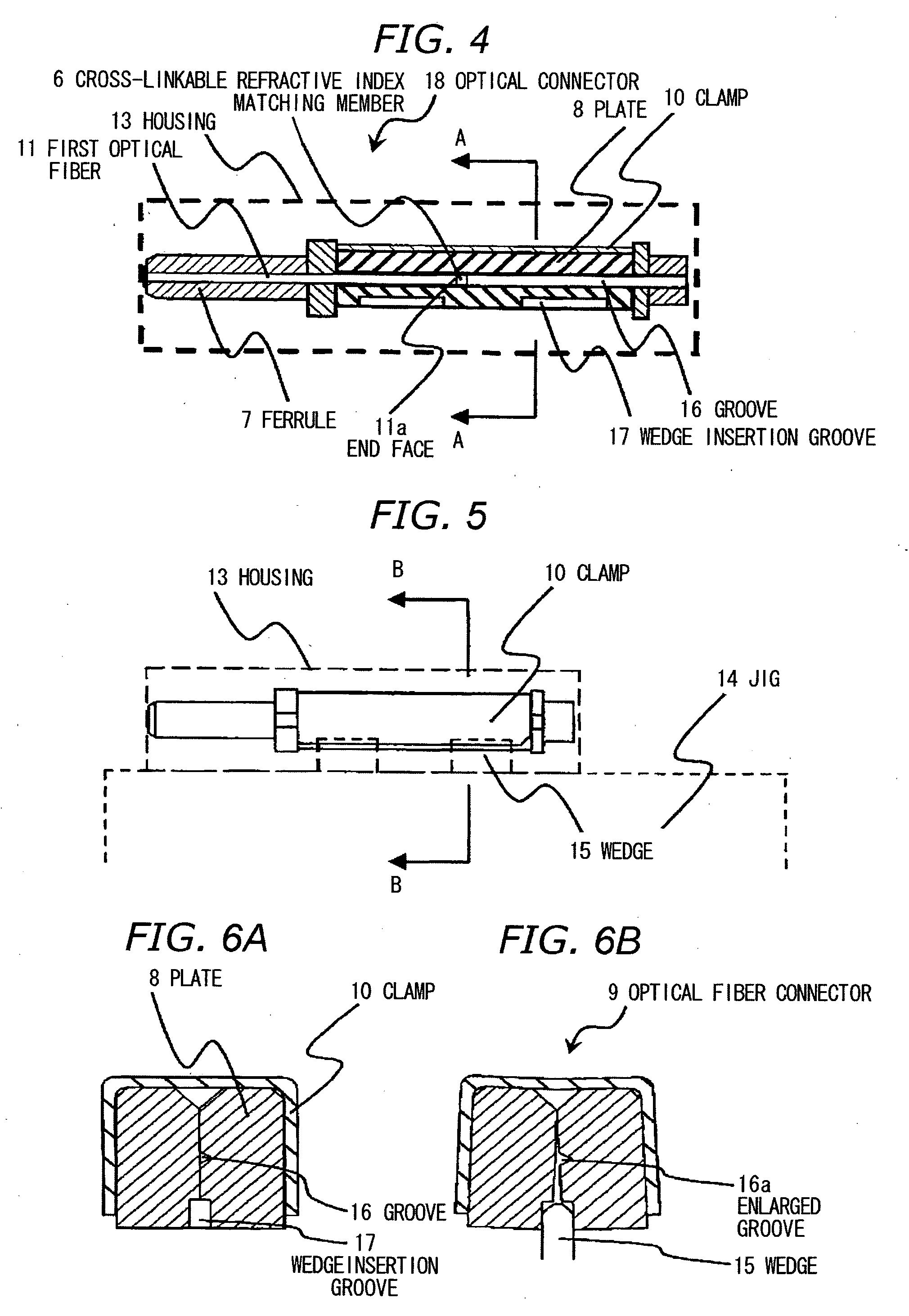
[0046]Further, the optical connector according to the invention comprises a structure that the cross-linkable refractive index matching member is attached to only the end face of the first optical fiber, so that the optical connector can achieve the following advantages (3) to (5). That is, if the cross-linkable refractive index matching member is also attached to the side face of the first optical fiber, when the back end portion of the first optical fiber attached with the cross-linkable refractive index matching member is set in the groove (V-shaped groove) the first optical fiber is likely to cause an axis misalignment to the second optical fiber. On the other hand, if the cross-linkable refractive index matching member is attached to only the end face of the first optical fiber, the axis misalignment between the first optical fiber and the second optical fiber can be prevented (advantage (3)). Further, if the cross-linkable refractive index matching member is also attached to the side face of the first optical fiber, when the back end portion of the first optical fiber attached with the cross-linkable refractive index matching member is to be set in the groove (the V-shaped groove), the cross-linkable refractive index matching member is attached to the groove (V-shaped groove) portion in which the second optical fiber 12 is to be set later, so as to exert a harmful influence to the setting of the second optical fiber. On the other hand, if the cross-linkable refractive index matching member is attached to only the end face of the first optical fiber, the harmful influence to the setting of the second optical fiber can be prevented (advantage (4)). Further, if the cross-linkable refractive index matching member is also attached to the side face of the first optical fiber, when the back end portion of the first optical fiber attached with the cross-linkable refractive index matching member is pressed from a top of the groove (V-shaped groove) the cross-linkable refractive index matching member in a side of the side face of the first optical fiber is split, so that when the first optical fiber is attached and removed repeatedly the split may grow up so as to reach the cross-linkable refractive index matching member. On the other hand, if the cross-linkable refractive index matching member is attached to only the end face of the first optical fiber, the disadvantage described above can be prevented (advantage (5)). Further, methods for attaching the cross-linkable refractive index matching member to only the end face of the first optical fiber may include a method comprising a step of conducting a water repellent finishing to the side face of the first optical fiber, so that when the cross-linkable refractive index matching member is coated on the end face of the first optical fiber the cross-linkable refractive index matching member can be prevented from entering the side face of the first optical fiber.
[0047]Further, the optical connector according to the invention comprises a structure that the cross-linkable refractive index matching member is attached over from the end face to the side face of the first optical fiber, so that the optical connector can achieve the following advantage. That is, if the cross-linkable refractive index matching member is attached to only the end face of the first optical fiber, when the second optical fiber is attached and removed the cross-linkable refractive index matching member may be separated from the end face of the first optical fiber. On the other hand, if the cross-linkable refractive index matching member is attached over from the end face to the side face of the first optical fiber, so that the separation can be prevented.

Problems solved by technology

In the physical connecting method (such as the connecting method using the mechanical splice and the connecting method using the optical connector), a profile of the end face of optical fiber can seriously affect its connection characteristics.
As a result, Fresnel reflection increases at the end face of the optical fiber to cause an increase in connection loss of the optical fiber.
However, of the conventional methods, the method of polishing the end face of the optical fibers or the ferrule is not suitable for connecting the optical fibers, especially an optical fiber (hereinafter called holey fiber) having plural periodical hole portions therein.
When the optical fibers are connected in a setting site, a lot of time consumption and labor charge are required for polishing the end face of the optical fibers etc., and a polishing device must be prepared for polishing the end face of the optical fibers etc.
Further, when the end face of the holey fiber is polished, a polishing residue generated in the polishing process and an abrasive agent used in the polishing process may enter the hole portion of the holey fiber to cause an increase in connection loss and a reduction in reliability.
Further, this method has the problem that, since the refractive index matching agent generally has a temperature dependency in refractive index, transmission loss of the holey fiber is extremely changed according to a change in refractive index of the refractive index matching agent entered into the hole portion of the holey fiber.
Furthermore, this method has the problem that, when the refractive index matching agent enters into the hole portion of the holey fiber, the refractive index matching agent between the end faces of the optical fibers decreases so that air gaps and air bubbles are easily generated between the end faces of the optical fibers to cause the significant lowering of optical characteristics of the holey fiber.
However, such a method is not suitable for connecting the optical fibers at the setting site since a dedicated connecting device is needed for performing the method and a lot of time consumption is required for sealing the hole portions at the end face of the holey fiber to cause an increase in connection cost of the optical fibers.
Therefore, when the optical fibers are connected each other at the setting site, a foreign substance such as a dust can easily adhere to the film to reduce reliability of the optical fiber and workability during the connection process of the optical fibers.

Method used


Image

  • Optical connector and connection structure of optical fibers
  • Optical connector and connection structure of optical fibers
  • Optical connector and connection structure of optical fibers

Examples


example 1

[0083]As a cross-linkable refractive index matching agent, an ethyl acetate 50% solution of an acrylic resin 100 weight parts comprising n-butyl acrylate / methyl acrylate / acrylic acid / 2-hydroxyethylmethacrylate copolymer (compounding ratio=82 / 15 / 2.7 / 0.3 (weight part)) and a cross-linking agent 1.0 weight part manufactured by Nihon Polyurethane Industry Co., Ltd and marketed under a trade name of “coronate L” were compounded and mixed together.

[0084]An optical transmission in a wavelength range of 1300 to 1600 nm of an cross-linkable refractive index matching member obtained by cross-linking and hardening the acrylic adhesive coating solution (the cross-linkable refractive index matching agent) obtained as described above, was measured by a spectral photometer. As a result of the measurement, the optical transmission of 93 to 95% was obtained. And a refractive index thereof is also measured by an Abbe refraction meter, so that a refractive index of 1.465±0.005 or less at a room temper...

example 2

[0092]As a cross-linkable refractive index matching agent, an addition type silicone based adhesive material coating liquid comprising SD4590 / BY24-741 / SRX212 / toluene (compounding ratio=100 / 1.0 / 0.9 / 50 (weight part)) is prepared (all of SD4590, BY24-741 and SRX212 are manufactured by Dow Corning Toray Co., LTd).

[0093]An optical transmission in a wavelength range of 1300 to 1600 nm of an cross-linkable refractive index matching member obtained by cross-linking and hardening the addition type silicone based adhesive material coating liquid (the cross-linkable refractive index matching agent) obtained as described above, was measured by a spectral photometer. As a result of the measurement, the optical transmission of 92 to 94% was obtained. And a refractive index thereof is also measured by an Abbe refraction meter, so that a refractive index of 1.465±0.005 or less at a room temperature (23±2° C.) was obtained.

[0094]Further, a breaking elongation thereof is also measured, so that the br...

example 3

[0109]As a cross-linkable refractive index matching agent, an ethyl acetate 50% solution of an acrylic resin 100 weight parts comprising n-butyl acrylate / methyl acrylate / acrylic acid / 2-hydroxyethylmethacrylate copolymer (compounding ratio=82 / 15 / 2.7 / 0.3 (weight part)) and a cross-linking agent 1.0 weight part manufactured by Nihon Polyurethane Industry Co., Ltd and marketed under a trade name of “coronate L” were compounded and mixed together.

[0110]An optical transmission in a wavelength range of 1300 to 1600 nm of an cross-linkable refractive index matching member obtained by cross-linking and hardening the acrylic adhesive coating solution (the cross-linkable refractive index matching agent) obtained as described above, was measured by a spectral photometer. As a result of the measurement, the optical transmission of 93 to 95% was obtained. And a refractive index thereof is also measured by an Abbe refraction meter, so that a refractive index of 1.465±0.005 or less at a room temper...


PUM


Abstract

An optical connector having: a ferrule into which a first optical fiber is inserted; an optical fiber connector disposed at an back end of the ferrule; and a cross-linkable refractive index matching member attached onto an end face on a back end side of the first optical fiber. The end face on the back end side of the first optical fiber and an end face of a second optical fiber to be inserted into the optical fiber connector from a back end side thereof are to be connected by a butting connection. The cross-linkable refractive index matching member is formed such that a cross-linkable refractive index matching agent is coated on the end face on the back end side of the first optical fiber, and the coated agent is cross-linked and hardened.

Description

[0001]The present application is based on Japanese patent application Nos. 200-44340 and 2006-44724, the entire contents of which are incorporated herein by reference.BACKGROUND OF THE INVENTION[0002]1. Field of the Invention[0003]This invention relates to an optical connector and, in particular, to an optical connector that is capable of easy connecting optical fibers in a setting site thereof. Also, this invention relates to a connection structure of optical fibers.[0004]2. Description of the Related Art[0005]At present, in order to connect optical fibers, a physical connecting method is widely used that is conducted by butting against each other end faces of the optical fibers or end faces of the ferrules which houses the optical fiber therein. The physical connecting method includes a connecting method using a mechanical splice and a connecting method using an optical connector. Generally, in case of permanent connection (i.e., the optical fibers are usually not detached after t...

Claims


Application Information

Patent Timeline
Patent Type & Authority Applications(United States)
IPC IPC(8): G02B6/36
CPCG02B6/02333G02B6/3846G02B6/3838G02B6/382
Inventor KATO, YOSHIHISASUZUKI, KANAKOSHIINA, NORIBUMINISIO, TOMOYUKIOHSONO, KAZUMASANAMEKAWA, YOSHIKAZUNAKATANI, YOSHIHIRO
Owner HITACHI METALS LTD
Why Eureka
Try Eureka