Vacuum Device, Operation Method For Vacuum Device, Exposure System, And Operation Method For Exposure System

Active Publication Date: 2007-08-30
NIKON CORP
View PDF9 Cites 14 Cited by
  • Summary
  • Abstract
  • Description
  • Claims
  • Application Information

AI Technical Summary

Benefits of technology

[0033] In this invention, for the same reasons as described in the seventh invention, the transmission of vibration from the pump to various parts inside and outside the lens barrel (e.g., mirrors, length gauges,

Problems solved by technology

Consequently, such deformation of the vacuum chamber is transmitted to the components such as stages, and thus causes a deterioration in the exposure performance (stage synchronization precision, aberration, variation in performance values, and the like).
Accordingly, such synthetic resin piping is undesirable.
However, since piping consisting of a material that has a high rigidity has a large bending radius, the piping layo

Method used


Image

  • Vacuum Device, Operation Method For Vacuum Device, Exposure System, And Operation Method For Exposure System
  • Vacuum Device, Operation Method For Vacuum Device, Exposure System, And Operation Method For Exposure System
  • Vacuum Device, Operation Method For Vacuum Device, Exposure System, And Operation Method For Exposure System

Examples


Embodiment Construction

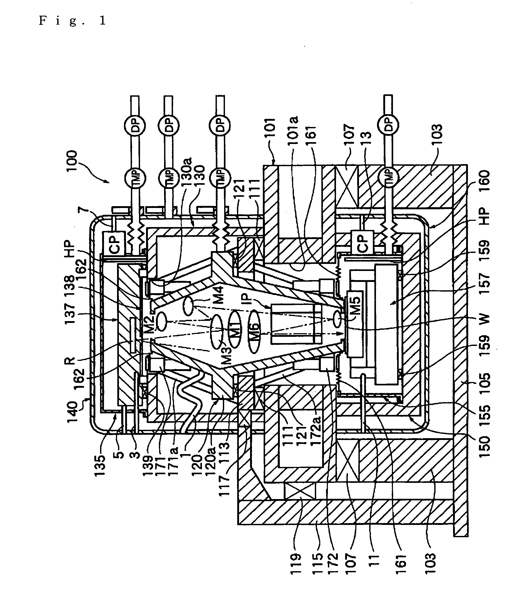
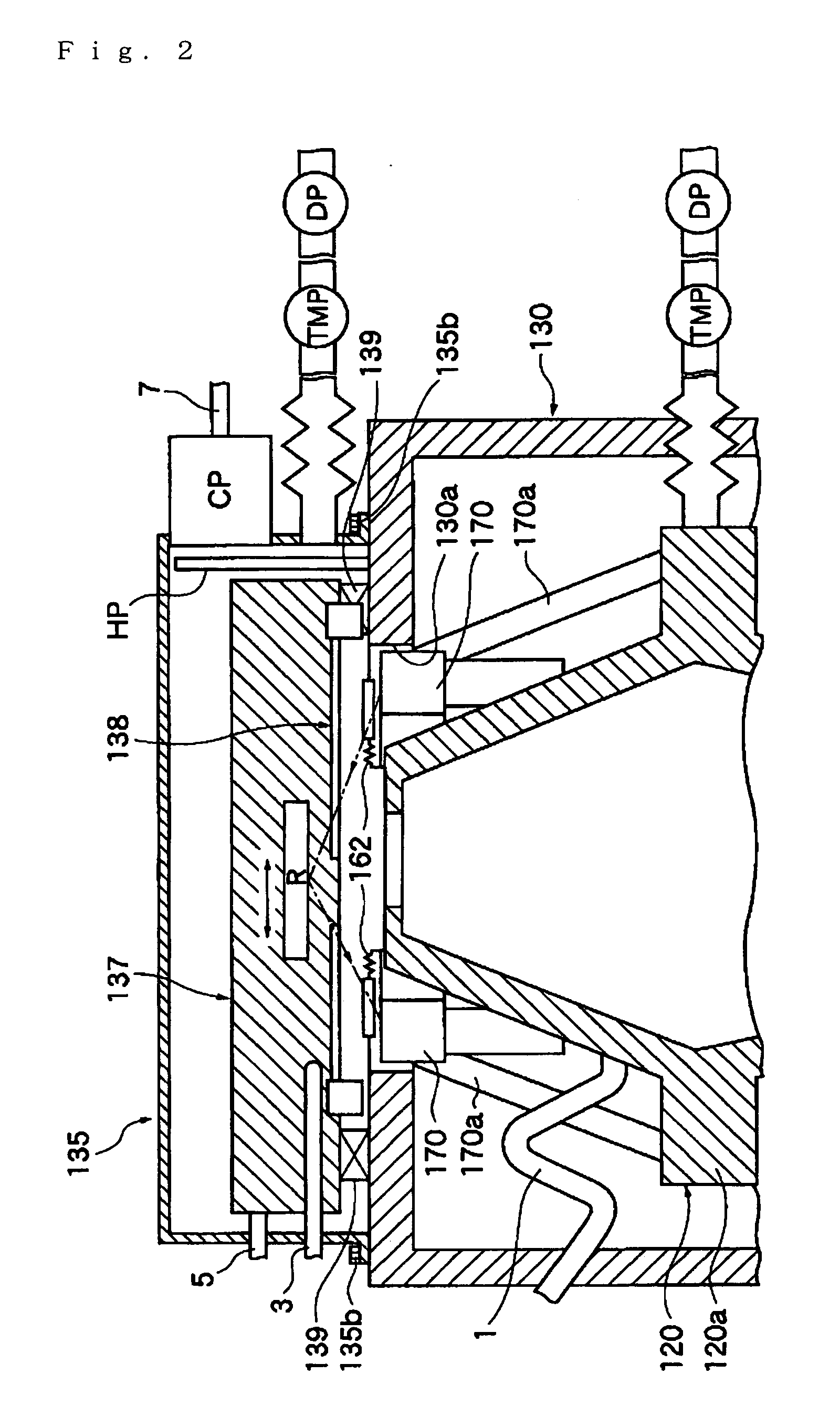
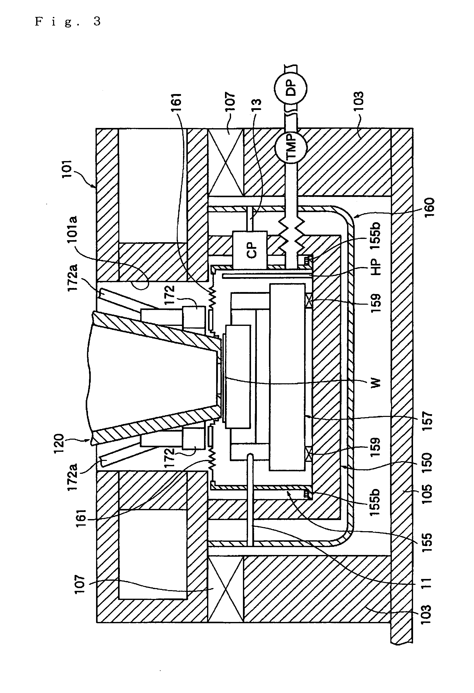
[0040] Working configurations of the present invention will be described in detail below with reference to the figures. FIG. 1 is a sectional view illustrating an example of the mechanical structure of an exposure apparatus constituting one working configuration of the present invention. FIG. 2 is a detailed diagram illustrating the construction of the upper part of the exposure apparatus shown in FIG. 1. FIG. 3 is a detailed diagram illustrating the construction of the lower part of the exposure apparatus shown in FIG. 1. FIG. 4 is a diagram illustrating in model form the construction of the area in the vicinity of the ion pump disposed inside the projection optical system lens barrel of the exposure apparatus shown in FIG. 1.

[0041] Furthermore, in the present working configuration, the system will be described using an EUVL exposure apparatus as an example. Although this is not shown in the respective figures, the EUV exposure apparatus comprises an illumination optical system wh...


PUM


Abstract

The exposure apparatus 100 comprises a double shell structure which has an upper vacuum chamber 140 on the outside of the reticle chamber 135, and a lower vacuum chamber 160 on the outside of the wafer chamber 155. A cryo pump CP and a turbo molecular pump TMP/dry pump DP are connected in parallel to each of the chambers, i.e., the reticle chamber 135 and wafer chamber 155. During exposure operation and alignment of the exposure apparatus 100, only the cryo pump CP (vibration-free type vacuum pump) is operated; the turbo molecular pump TMP/dry pump DP (vibrating type vacuum pump) is stopped. As a result, it is possible to cut off the transmission of vibration from the vibrating type vacuum pump during exposure operation and alignment of the exposure apparatus, so that the precision of the stage devices 137 and 157 can be ensured to a much greater degree; accordingly, deterioration of the exposure performance can be reduced to a much greater extent.

Description

TECHNICAL FIELD [0001] The present invention relates to a vacuum apparatus equipped with components such as a stage apparatus that are operated in a vacuum, an exposure apparatus which transfers a pattern formed on an original plate onto a sensitive substrate using energy radiation such as EUV light (extreme ultraviolet light), and operating methods for these apparatuses. BACKGROUND ART [0002] In recent years, as semiconductor integrated circuits have become progressively finer, projection lithography techniques using EUV light which has a wavelength of approximately 13 nm have been developed in order to increase the resolving power of optical systems, which is limited by the diffraction limit of light. Such EUV exposure apparatuses comprise a lens barrel which accommodates a projection optical system that projects the pattern on the original plate onto the sensitive substrate, an original plate stage which moves and positions the original plate, a sensitive substrate stage which mo...

Claims


Application Information

Patent Timeline
IPC IPC(8): F26B13/30H01L21/027G03F7/20
CPCG03F7/70841G03F7/70808
Inventor TANAKA, KEIICHI
Owner NIKON CORP
Why Eureka
Try Eureka