

Dielectric ceramic composition and the production method
a technology of dielectric ceramics and compositions, applied in ceramics, fixed capacitors, electrical equipment, etc., can solve the problems of affecting the production process, so as to achieve excellent q value and insulation resistance, improve the high temperature accelerated lifetime, and improve the effect of accelerated li
- Summary
- Abstract
- Description
- Claims
- Application Information
AI Technical Summary
Benefits of technology
Problems solved by technology
Method used
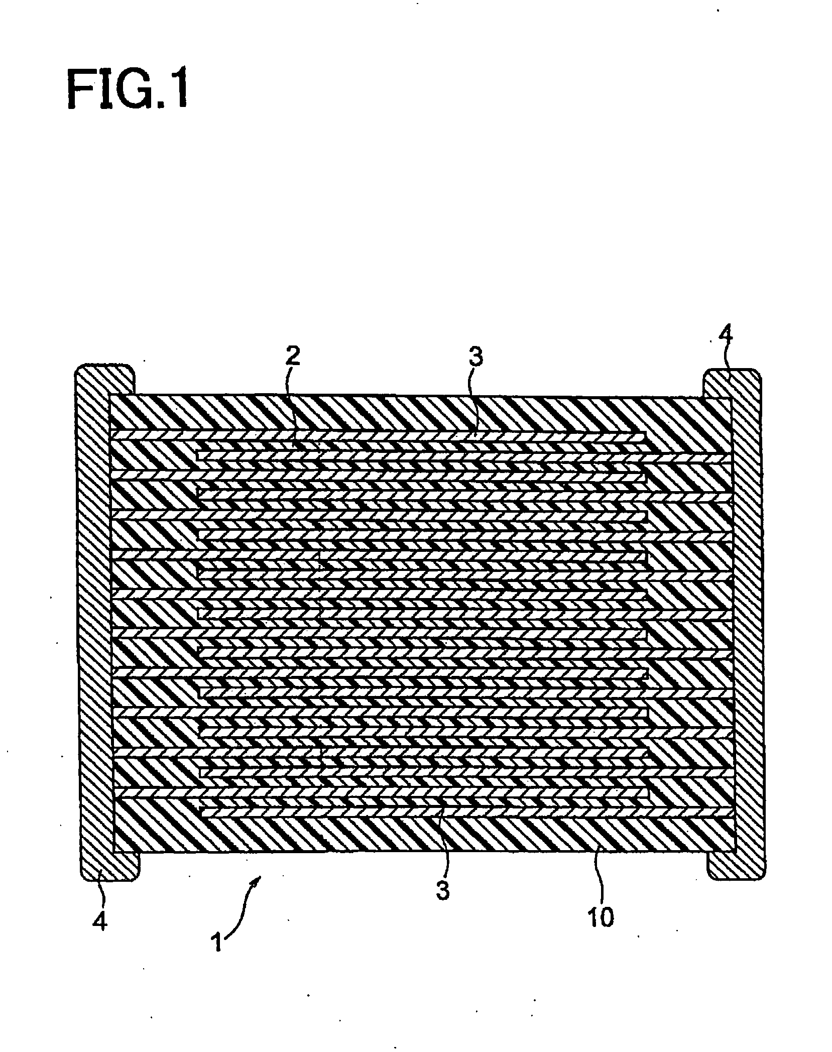
Image

Examples
example 1
[0101]First, a main component material was obtained by compounding respective oxides and carbonate (CaCO3, SrCo3, Zro2 and TiO2) so as to obtain a dielectric oxide expressed by the composition formula of ((Ca0.70 Sr0.30)O—(Zr0.97 Ti0.03)O2).
[0102]Next, Li—W—B—Si-0 glass as a sintering auxiliary produced in advance was added in an amount of 3 moles with respect to 100 moles of the obtained main component material, wet mixed by a ball mill and dried to obtain a dielectric ceramic composition material. Note that the Li—W—B—Si—O glass as a sintering auxiliary was produced as below. First, oxides of respective components, which are Li2O, WO3, B2O3 and SiO2 were compounded so as to obtain a predetermined composition. Next, the result is wet mixed by a ball mill for 16 hours and pulverized, then, dried by evaporating, and a powder after drying was fired at 1000° C. in the air for two hours. After that, fine pulverization was performed to obtain a glass compound powder having an average par...
example 2
[0130]Other than using Li—V—B—Si—O glass (Li2O: 11 parts by weight, V2O5: 6 parts by weight, B2O3: 23 parts by weight and SiO2: 60 parts by weight) as a sintering auxiliary, capacitor samples were produced in the same way as in the example 1 and evaluated in the same way as in the example 1. Note that a total of 5 kinds of samples were produced in the example 2, wherein the temperature raising rates at firing were rates shown in Table 2 when producing the samples. The results are shown in Table 2.
[0131]Table 2
TABLE 2TemperatureContent RatioRaising Rateof V ElementSampleSecondat Firing [° C. / T15T30T50IRHALTNo.Componenthour][%][%][%]Q Value[Ω][hour]11ComparativeV2O510083.782.380.95,0231.3 × 10114Example12ExampleV2O530065.657.052.48,6844.8 × 10126313ExampleV2O550046.640.236.410,5961.2 × 101311514ExampleV2O570018.57.75.014,6901.5 × 101316415ComparativeV2O580010.43.42.36,9484.0 × 101125Example
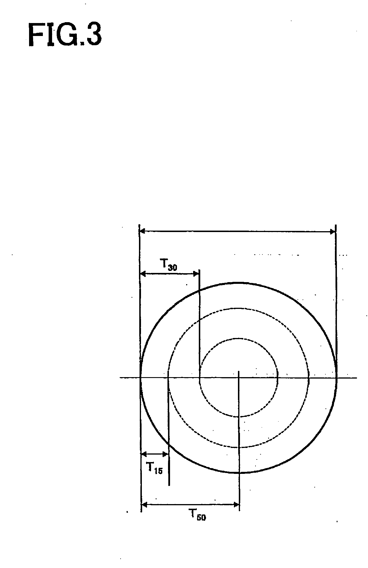
[0132]In Table 2, content ratios of V element at depths T15, T30 and T50 are on an assumption th...
example 3
[0134]Other than using Li—Mo—B—Si—O glass (Li2O: 11 parts by weight, MoO3: 6 parts by weight, B2O3: 23 parts by weight and SiO2: 60 parts by weight) as the sintering auxiliary, capacitor samples were produced in the same way as in the example 1 and evaluated in the same way as in the example 1. Note that a total of 5 kinds of samples were produced in the example 3, wherein the temperature raising rates at firing were rates shown in Table 3 when producing the samples. The results are shown in Table 3.
[0135]Table 3
TABLE 3TemperatureContent RatioRaising Rateof Mo ElementSampleSecondat Firing [° C. / T15T30T50IRHALTNo.Componenthour][%][%][%]Q Value[Ω][hour]16ComparativeMoO310084.383.482.14,9362.7 × 10115Example17ExampleMoO330066.256.353.08,3336.6 × 10125818ExampleMoO350047.241.137.610,4292.2 × 101312719ExampleMoO370019.58.05.213,9812.0 × 101315220ComparativeMoO380011.24.32.97,3496.7 × 101129Example
[0136]In Table 3, content ratios of Mo element at depths T15, T30 and T50 are on an assumpti...
PUM
| Property | Measurement | Unit |
|---|---|---|
| holding temperature | aaaaa | aaaaa |
| temperature | aaaaa | aaaaa |
| length | aaaaa | aaaaa |
Abstract
Description
Claims
Application Information