Method for preparing silicon carbide single crystal

a silicon carbide and single crystal technology, applied in the direction of crystal growth process, polycrystalline material growth, protective fluid, etc., to achieve good quality, high speed, and good quality

Inactive Publication Date: 2007-09-13
NIPPON STEEL CORP
View PDF18 Cites 39 Cited by
  • Summary
  • Abstract
  • Description
  • Claims
  • Application Information

AI Technical Summary

Benefits of technology

[0025] This invention provides a method for producing a SiC single crystal which makes it possible to produce a good quality SiC single crystal containing no inclusions inside it at a high speed. It is anticipated that ...

Problems solved by technology

However, since repeated heating and cooling consumes a large amount of thermal ene...

Method used


Image

  • Method for preparing silicon carbide single crystal
  • Method for preparing silicon carbide single crystal
  • Method for preparing silicon carbide single crystal

Examples


example 1

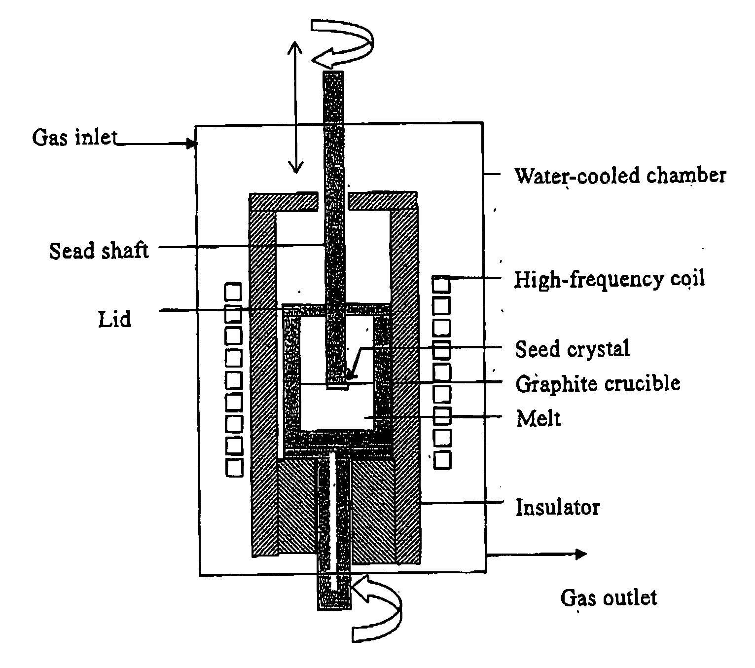
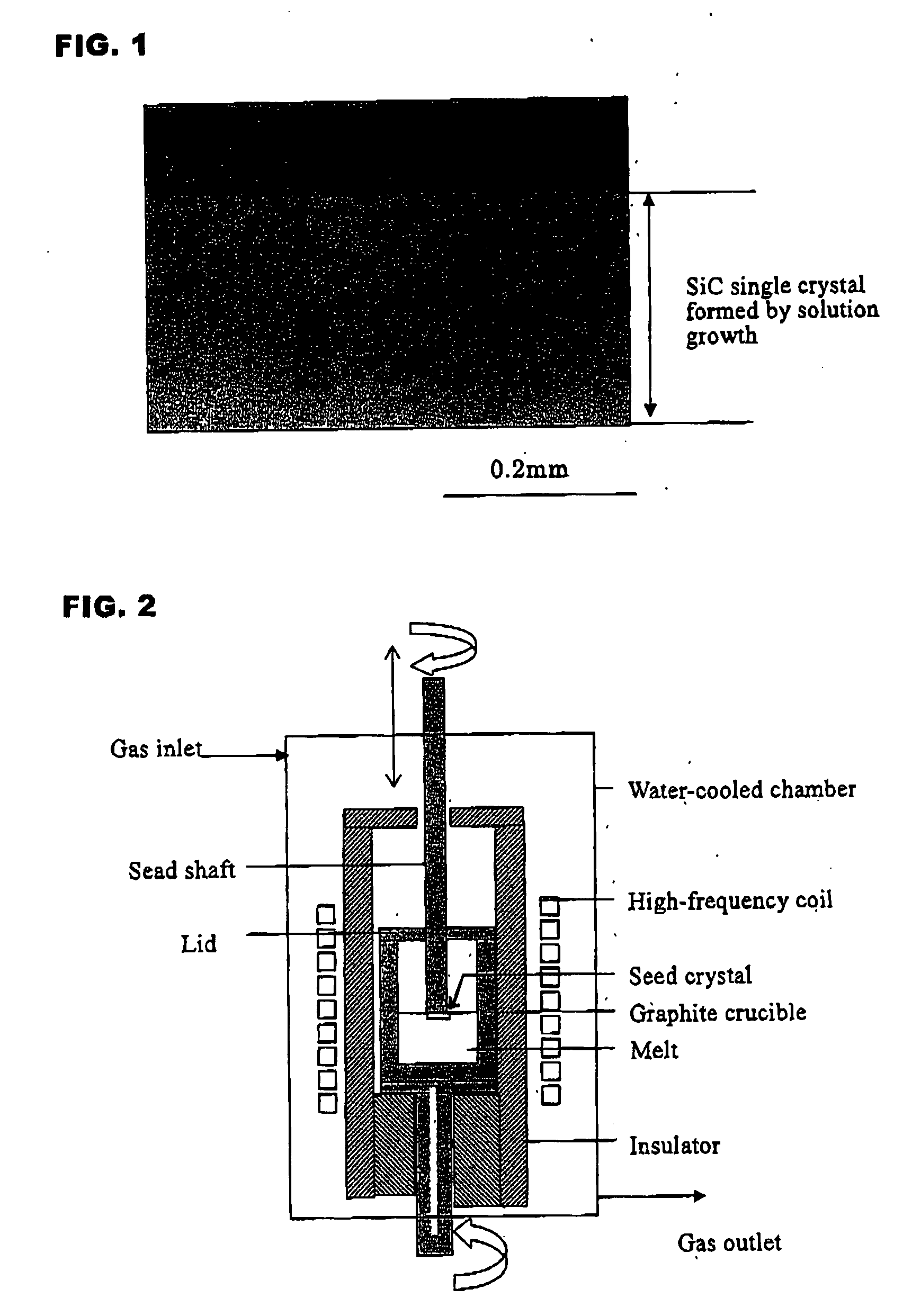
[0128] This example illustrates application of ACRT in which only a graphite crucible is rotated in back and forth.

[0129] A graphite crucible was charged with Si and Ti as an alloy raw material (for forming a solvent for SiC) in proportions corresponding to a composition of Si0.80Ti0.20 ([M] / ([M]+[Si])=0.20), and after the atmosphere inside the apparatus was replaced with argon gas, the raw material was heated to melt. Heating of the melt was adjusted such that the temperature in the vicinity of the level of the melt which became a crystal growth interface was approximately 1700° C. and the temperature at the bottom of the melt was approximately 1750° C. The crucible was rotated from the start of heating. Heating of the melt was continued for two hours so that a sufficient amount of carbon was dissolved from the crucible into the melt to achieve a saturated SiC concentration, and then a SiC seed crystal attached to a seed shaft was immersed just below the level of the melt.

[0130] ...

example 2

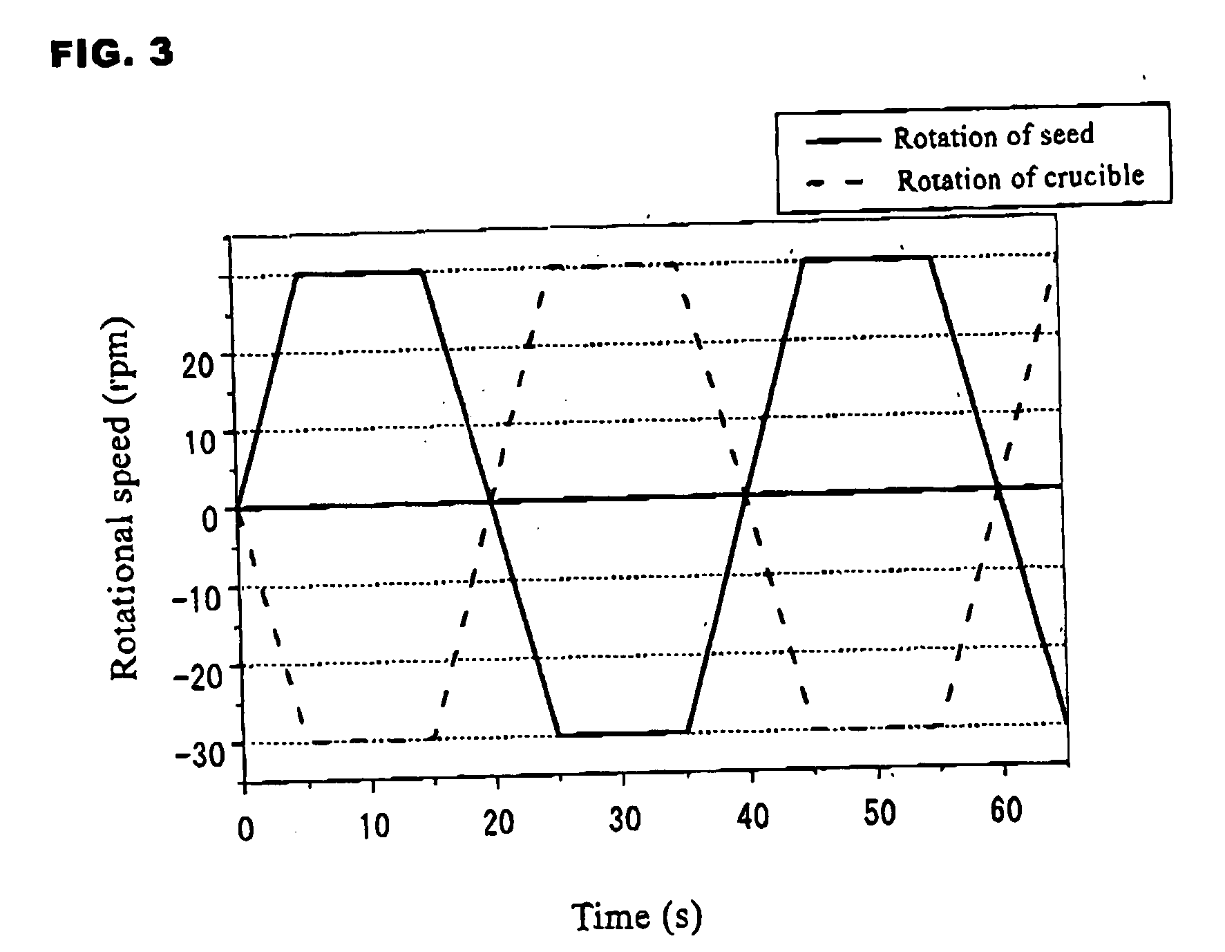
[0132] This example illustrates growth of a SiC single crystal by ACRT in which a graphite crucible and a seed crystal (seed shaft) are rotated with back-and-forth rotation in such a manner that they have the same rotational direction.

[0133] The seed crystal and the crucible were first both rotated to the left. The final rotational speed of the seed crystal and the crucible was set at 30 rpm, and the time until the set rotational speed was reached was 5 seconds. After the final rotational speed was reached, rotation was carried out at this rotational speed for 10 seconds, and then rotation was stopped in 5 seconds. Next, the rotational direction of the seed crystal and the crucible was changed to the right, and in the same manner as described above, it reached 30 rpm in 5 seconds, and after rotation was maintained at 30 rpm for 10 seconds, rotation was stopped in 5 seconds. The above procedure was made one cycle (cycle time of 40 seconds), and this cycle was repeated during crystal...

example 3

[0135] This example illustrates growth of a SiC single crystal by ACRT in which a graphite crucible and a seed crystal (seed shaft) are rotated with back-and-forth rotation in such a manner that their rotational directions are opposite from each other.

[0136] Thus, the seed crystal was first rotated to the right, while the crucible was rotated to the left. The final rotational speed for each was set at 30 rpm, and the time to reach the set rotational speed was 5 seconds. After the set rotational speed was reached, rotation was continued at that rotational speed for 10 seconds, and then rotation was stopped in 5 seconds. Next, the rotational directions were reversed such that the seed shaft was rotated to the left and the crucible was rotated to the right. In the same manner as described above, after 30 rpm was reached in 5 seconds, rotation was continued at 30 rpm for 10 seconds, and then rotation was stopped in 5 seconds. The above procedure was made one cycle, and this cycle was r...


PUM


Abstract

A SiC single crystal is produced by the solution growth method in which a seed crystal attached to a seed shaft is immersed in a solution of SiC dissolved in a melt of Si or a Si alloy and a SiC single crystal is allowed to grow on the seed crystal by gradually cooling the solution or by providing a temperature gradient therein. To this method, accelerated rotation of a crucible is applied by repeatedly accelerating to a prescribed rotational speed and holding at that speed and decelerating to a lower rotational speed or a 0 rotational speed. The rotational direction of the crucible may be reversed each acceleration. The seed shaft may also be rotated synchronously with the rotation of the crucible in the same or opposite rotational as the crucible. A large, good quality single crystal having no inclusions are produced with a high crystal growth rate.

Description

TECHNICAL FIELD [0001] This invention relates to a method for producing a good quality single crystal of silicon carbide suitable as a material for optical devices and electronic devices, and particularly to a method which can produce a good quality silicon carbide single crystal at a high growth rate with certainty by the solution growth method. BACKGROUND ART [0002] Silicon carbide (SiC) is a type of compound semiconductor which is thermally and chemically stable. It has properties which are advantageous compared to those of silicon (Si) in that it has approximately three times the band gap, approximately ten times the dielectric breakdown voltage, approximately two times the electron saturation speed, and approximately three times the thermal conductivity of Si. On account of these superior properties, it is anticipated that SiC will be capable of use as a material for electronic devices such as power devices which overcomes the physical limits of Si devices and environmentally r...

Claims


Application Information

Patent Timeline
IPC IPC(8): C30B15/00C30B19/00
CPCC30B9/06C30B9/10C30B15/305C30B17/00C30B19/02Y10T117/1072C30B29/36Y10T117/1004Y10T117/10Y10T117/1008Y10T117/1016C30B19/04
Inventor KUSUNOKI, KAZUHIKOKAMEI, KAZUHITOYASHIRO, NOBUYOSHIYAUCHI, AKIHIROUEDA, YOSHIHISAITOH, YUTAKAOKADA, NOBUHIRO
Owner NIPPON STEEL CORP
Why Eureka
Try Eureka