Hub cap

a hubcap and hub technology, applied in the direction of disc wheels, wheel protection, vehicle components, etc., can solve the problems of reduced grip on the lug nuts, increased manufacturing costs, and shortened service life of the lug cap, so as to reduce the susceptibility of member breakage, enhance flexural resistance, and increase assembly tolerance

Inactive Publication Date: 2007-09-13
FLORIDA PRODION ENG
View PDF11 Cites 19 Cited by
  • Summary
  • Abstract
  • Description
  • Claims
  • Application Information

AI Technical Summary

Benefits of technology

[0007] The resiliently biased configuration of the lug nut engaging members may be due to, for example, a cantilevered construction of the members relative to the body. By engaging the lug nut, the lug nut engaging members radially deflect to an extent necessary to cooperate with one another to keep the hub cap attached to the wheel. Each of the lug nut engaging members includes a substantially arcuate base configured to engage axially at least one surface of the lug nut, and a substantially arcuate crown axially aligned with and disposed axially inward relative to the substantially arcuate horizontal base. Inherent in an arcuate structure is the partial, bow-like contact area with the device it surrounds. By having only a portion of the circumference of a lug nut engaged rather than substantially full circular contact area, the present lug nut engaging members provide more assembly tolerance, as well as reduced susceptibility to member breakage. In the present context, the term “substantially” is utilized to represent the inherent degree of uncertainty that may be attributed to any quantitative comparison, value, measurement, or other representation. As such, it refers to an arrangement of elements or features that, while in theory would be expected to exhibit exact correspondence or behavior, may in practice embody something slightly less than exact. The term also represents the degree by which a quantitative representation may vary from a stated reference without resulting in a change in the basic function of the subject matter at issue.
[0009] In one variant of the hub cap design, the lug nut engaging members can be integrally formed with the body portion to define a one-piece hub cap design. In another variant, the lug nut engaging members are integrally formed with one another on a common ring, which in turn can be removably attachable to the body portion, thereby resulting in a two-piece hub cap design. In this latter configuration, a boss can be formed on the inner surface of the hub cap body portion. The boss can define an aperture therein to allow passage of projecting connectors (also referred to as projections) situated on the ring. In one form, the projections are resiliently-biased snap-fit detents that are integrally formed in the ring. At least one of the ring and the hub cap can be made from a plastic, ceramic or continuous or discontinuous reinforced composite based on plastic or ceramic. In situations where excessive heat soaking may be experienced, the ring can be molded from a separate, higher-temperature plastic, ceramic or composite material, such as a glass-reinforced nylon. To enhance the outward appearance of the hub cap, a metallic (for example, chrome or chrome-like) coating may be used in the body portion. In another form, colors may be painted onto or molded in the body portion to enhance its appearance.
[0010] In the one-piece variant of the hub cap, the lug nut engaging members form a substantially cantilevered attachment to the body portion. In this way, the base forms a proximal end (i.e., closest to the point of connection between the body portion and the lug nut engaging members), while the crown defines a distal end. The inherent flexibility in a cantilever structure allows the distal portion adjacent the crown to move radially relative to the proximal end and the body portion. As with the two-piece variant discussed above, plastic, ceramic or composite materials may be used. Also as with the two-piece variant discussed above, the outward appearance of the hub cap can be augmented by the addition of a metallic coating, painted-on coating or through molded-in color.
[0011] According to another aspect of the invention, a hub cap, comprising a body portion and a wheel coupling portion, is disclosed. The body portion defines an inner surface and an outer surface. The inner surface comprises a boss with an aperture that allows the wheel coupling portion to be removably attachable. The wheel coupling portion includes a ring, numerous circumferentially spaced and resiliently biased lug nut engaging members disposed on the ring, and a plurality of projections disposed on the ring. The projections are oriented to engage the boss aperture to facilitate connection between the wheel coupling portion and the body portion. The lug nut engaging members extend axially inward and are alignable with corresponding lug nuts disposed on a wheel. Each of these members includes a proximal end, defining a base configured to engage axially a corresponding one of the lug nuts, and a distal end, defining a substantially arcuate crown axially aligned with, and disposed axially inward relative to, the base. In this way, radial deflections imparted to each of the crowns by the lug nuts promote a secure connection between the hub cap and the wheel.

Problems solved by technology

While the use of highly decorative hub caps is in its ascendancy, difficulties in reliably and inexpensively securing these hub caps to the underlying wheel or lug nuts used to secure the wheel to an axle jeopardize their long-term viability.
The use of such adhesives, while potentially beneficial for thermal protection of, and acoustic enhancement to, wheel covers, necessitates relatively detailed placement and assembly procedures to ensure weight minimization, adequate affixation and dynamic balancing, with concomitant increases in manufacturing costs.
Nevertheless, the fasteners, which are typically in the form of cantilevered, tubular cups with segmented, finger-like extensions formed on the inner surface of the hub cap can soften, creep or otherwise suffer reduced grip on the lug nuts as a result of high temperature and rotational loads.
These conditions result from wheel rotation and braking.
Furthermore, differences in the rate of thermal expansion of the metallic wheel and the plastic hub cap can exacerbate an already loose or weakened fastener connection.
In addition, individual fingers within the fasteners may be susceptible to breakage due to improper alignment, mounting and handling.
While such a construction may have the advantage of better resistance to the buildup of heat, it does so with increases in weight and cost through the use of stamped metal parts that may require coating or related environmental protection to avoid the effects of rust or related corrosion.
Moreover, schemes to attach the fasteners to the hub cap may be susceptible to heat or vibration-induced wear and subsequent separation, as friction-fit connections can work their way loose over extended periods of operation.

Method used


Image

  • Hub cap
  • Hub cap
  • Hub cap

Examples


Embodiment Construction

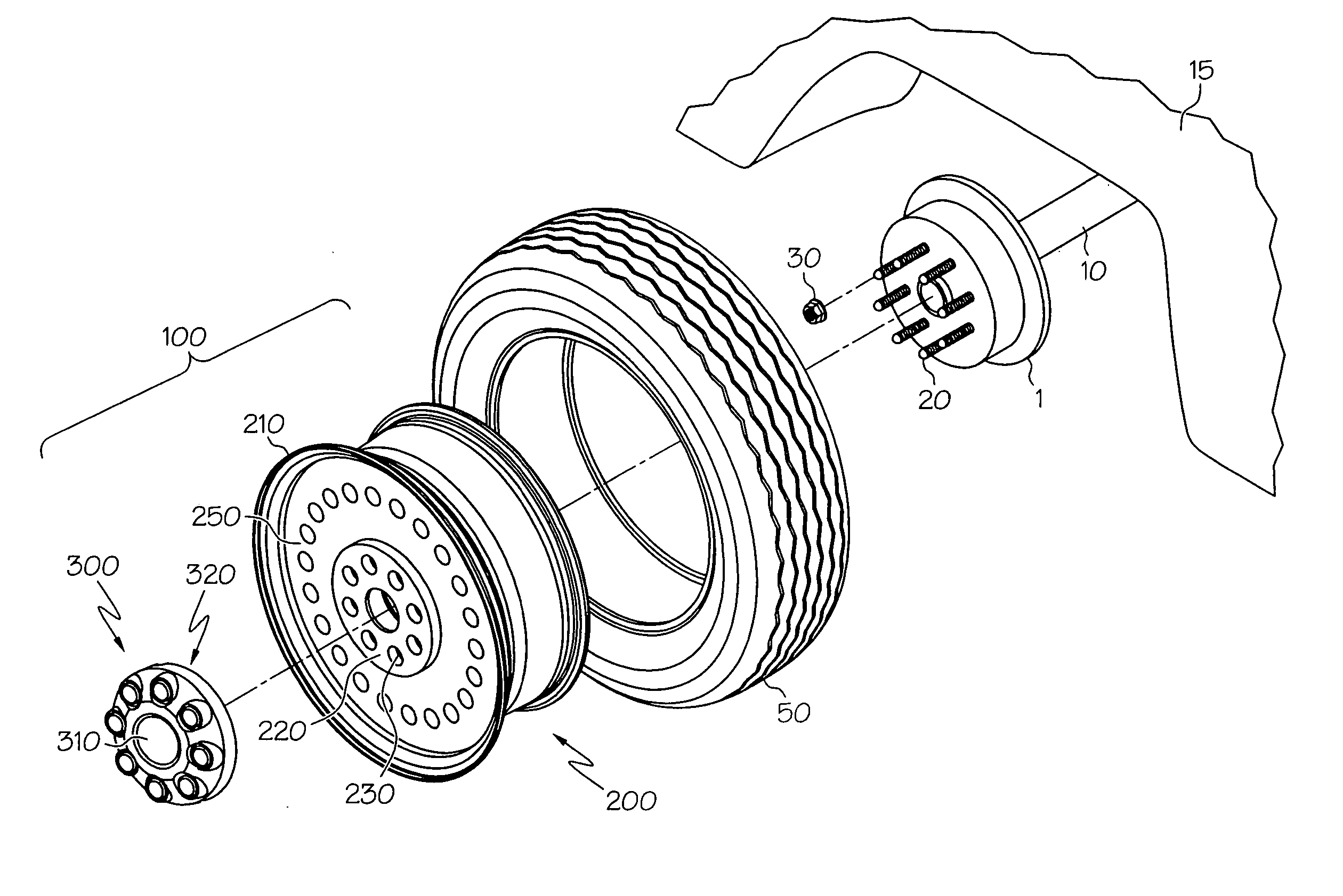
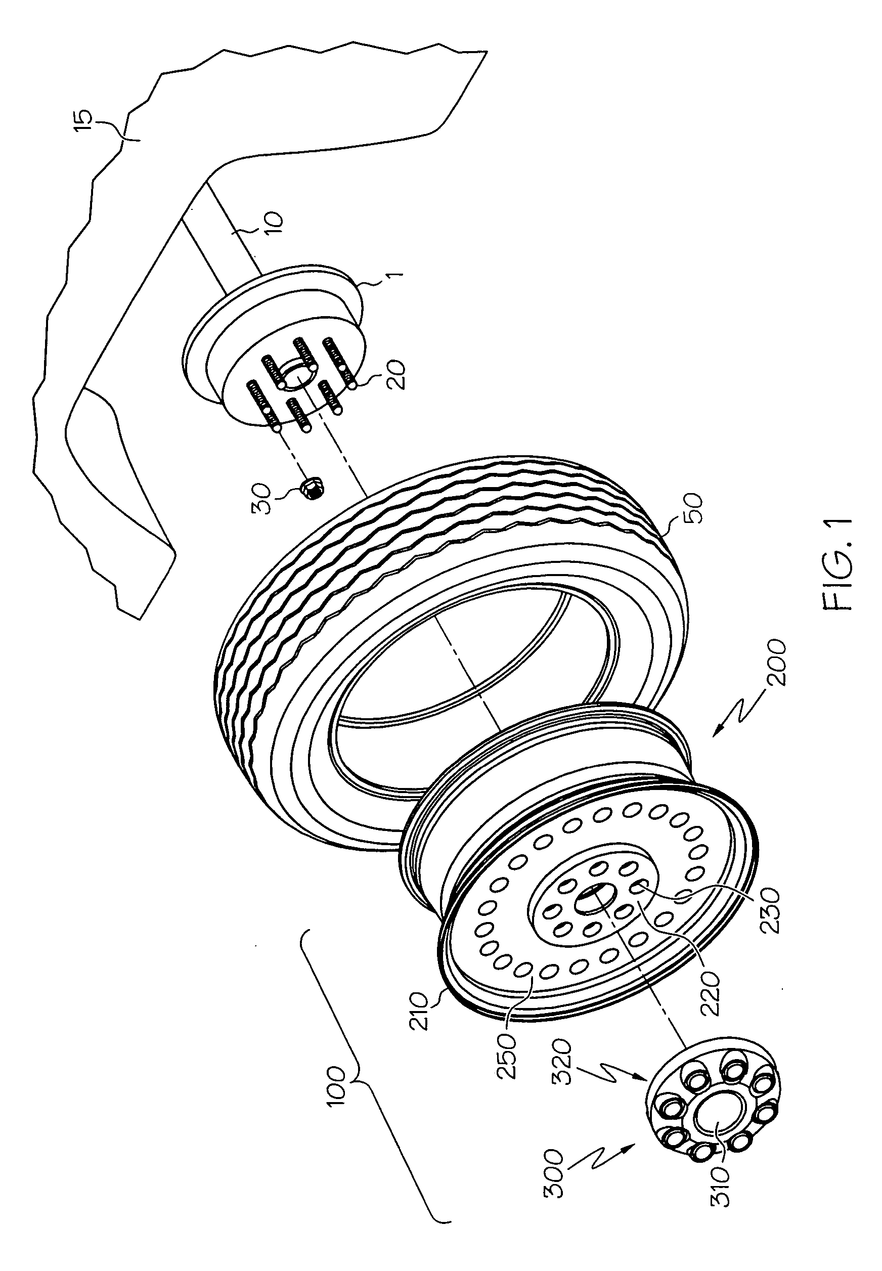
[0029]FIG. 1 is an outward-facing exploded view of a wheel assembly 100 with wheel 200 and hub cap 300, both configured to be mounted to a hub 1 and axle 10 of vehicle 15. The wheel 200 includes a rim (or flange) section 210, central hub section 220 with lug-receiving holes 230 and central bore 240, and web (or spoke) section 250. Hub 1 includes holes therein (not shown) to allow threaded placement of lugs 20 which in turn allow threaded attachment of lug nuts 30. The corresponding holes 230 formed in wheel 200 allow placement of lugs 20 through the aligned holes, while accompanying lug nuts 30 secure the wheel 200 to the hub 1 through the lugs 20. A tire 50 is also mounted onto the rim section 210 of wheel 200.

[0030] In a preferred (although not necessary) embodiment, the hub cap 300 is made from a non-metallic material, such as plastic or related resin, examples of which may include acrylonitrile-butadiene-styrene (ABS), polycarbonate or a combination thereof. The material may fu...


PUM


Abstract

A hub cap for a vehicular wheel. The hub cap includes a body portion and a wheel coupling portion, both made from a non-metallic material. The wheel coupling portion has circumferentially-spaced lug nut engaging members that are axially alignable with lug nuts extending from the wheel. The lug nut engaging members form a substantially arcuate shape, and are resiliently biased so that upon placement of the hub cap onto a wheel, the lug nuts push the lug nut engaging members in a radial direction. Continued contact between the lug nuts and their corresponding engaging members promotes secure connection between the hub cap and wheel. In one embodiment, the body portion and wheel engaging portion is formed from two separate pieces that are subsequently joined, while in another, they are formed from a single unitary structure to define a one-piece construction.

Description

BACKGROUND OF THE INVENTION [0001] This invention relates generally to a vehicular hub cap, and more particularly to attachment features formed in a hub cap to enhance attachment integrity under harsh environmental conditions. [0002] Decorative wheel covers form an important part of a vehicle's appeal, and can be used to cover portions or all of an outward-facing surface of a vehicular wheel. Such covers allow conventional fabricated steel wheels to emulate the aesthetically-pleasing attributes of polished, chrome-plated or cast aluminum wheels at a small fraction of the cost. Most wheels for such applications include a rim section, a spoke (or web) section and a central hub section, the latter of which allows for connection between the wheel and an axle. The hub section is one area of the wheel's outward-facing surface that can especially benefit from decorative covers, as otherwise unsightly lugs, lug nuts and axle spindles are left exposed. Wheel covers that overlie the hub secti...

Claims


Application Information

Patent Timeline
Patent Type & Authority Applications(United States)
IPC IPC(8): B60B7/14
CPCB60B3/16B60B7/0013B60B7/004B60B7/0046B60B7/12B60B7/04B60B7/068B60B7/08B60B7/0093
Inventor ROGERS, DENNIS ROGER
Owner FLORIDA PRODION ENG
Why Eureka
Try Eureka