Optical Scanning System

a scanning system and optical technology, applied in the field of optical scanning system, can solve the problems of limited signal strength, short interaction length between bio-samples, and high background or nois

Active Publication Date: 2007-09-13
LDIP LLC
View PDF99 Cites 64 Cited by
  • Summary
  • Abstract
  • Description
  • Claims
  • Application Information

AI Technical Summary

Benefits of technology

[0024]In one embodiment of the system the substrate further includes one or more microchannel and one or more reservoirs in fluid communication with one or more optical sensing site. In one embodiment the system further includes a fluidics layer coupled to the substrate and comprising one or more microchannel and one or more reservoirs in fluid communication with one or more optical sensing site.
[0025]In another aspect the invention provides scanning sensing method including delivering a sample suspected of containing a biologically active analyte to be detected to an optical sensing site of a scanning sensor system, providing a first light wave using a switchable light source to one or more of a plurality of substantially parallel excitation waveguides in optical communication with the optical sensing site, wherein the first light wave is transducable by a sensor associated with the optical sensing site to a second light wave carried in one or more of a plurality of substantially parallel collection waveguides in optical communication with the optical sensing site and crossing the excitation waveguides. The method further includes detecting a measurable change in the second light wave using a detector in optical communication with the collection waveguides, wherein a measurable change in the first light waves occurs when the sensor interacts with the biologically active analyte.
[0026]In one embodiment scanning sensing further includes switching one or more input light wave from the switchable light source into the substrate to produce the first light wave in one or more of the excitation waveguides. In a particular embodiment the switchable light source includes an optical switch for controlled switching of one or more input light wave, the optical switch can multicast light to a plurality of outputs and into the substrate to controllably produce the first light wave in one or more of the excitation waveguides. In one embodiment the switchable light source includes an array of individually controlled light generators for controlled switching of one or more input light wave, to controllably produce the first light wave in one or more of the excitation waveguides.

Problems solved by technology

This arrangement suffers from several inherent limitations including a very short interaction length between the bio-sample and the light (usually a single mono-layer).
This limits the signal strength and thus the SNR.
Another limitation is a high background or noise due to the fact that the back reflected light and the emitted fluorescent light travel in the same direction.
A further limitation is high sensitivity to the planarity and the position of the chip that need to be maintained in focus.
Still another limitation is slow operation due to the need to have large enough number of ‘pixels’ (scanned spots) within every sample and long enough integration time.
Yet another limitation is the need for a complicated optical and mechanical structure that entails bulky and expensive systems.
One drawback of this kind of systems is relatively poor performance due to uniformity of excitation as well as collection of the light.
This leads to non-repeatable results.
Another drawback is high noise levels due to crosstalk between the different spots.
A further drawback is that large spots and relatively small numbers of elements are required to generate signal large enough for efficient imaging with the CCD.
Yet another drawback is the long integration time to overcome SNR issues.
The major problems associated with this type of systems include non-specificity due to inability to recognize the exact reason for the index change which may occur from other material deposition as well as temperature changes.
Another problem is a very slow speed in addressing the different elements which disqualify this method for running large numbers of element arrays.

Method used


Image

  • Optical Scanning System
  • Optical Scanning System
  • Optical Scanning System

Examples


##ic example 1

Prophetic Example 1

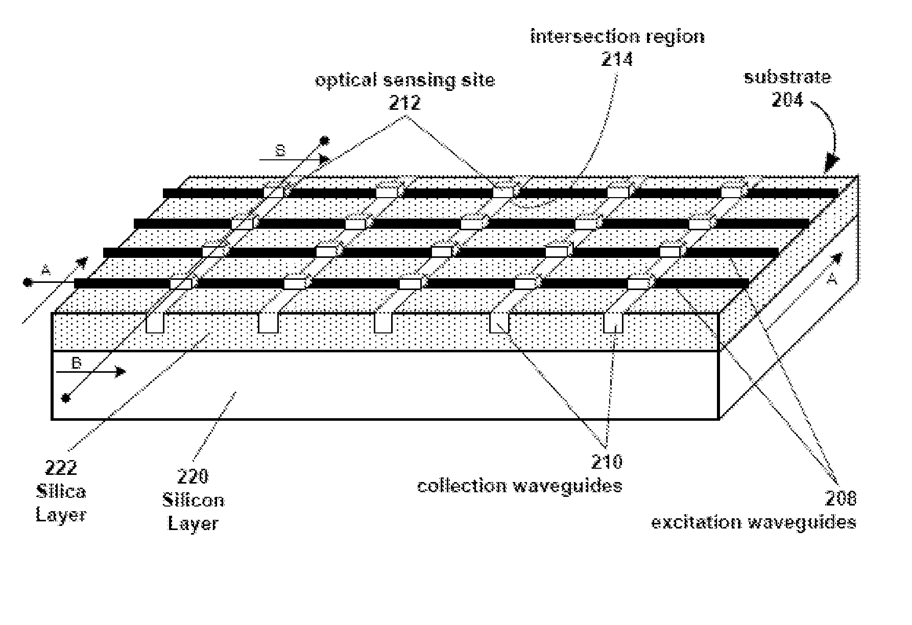
[0241]Quantitative real-time PCR detection of transcripts, for example, bcr / abl fusion transcripts, can be achieved using a scanning sensing system such as the example illustrated in FIG. 1A using a PCR assay protocol modified from that described by Kreuzer et al. (supra). The system includes a substrate chip with excitation waveguides, collection waveguides and intersection regions. The intersection regions where the excitation waveguides and collection waveguides cross include optical sensing sites with sensing wells for conducting quantitative real-time PCR. The scanning sensing system further includes a dynamic switchable light source coupled to the substrate and the excitation waveguides. The system further includes an optical detector.

[0242]Samples suspected of containing RNA transcripts of interest (e.g., blood from a subject) are treated to obtain a source of total RNA which is subsequently reverse transcribed using reverse transcriptase into cDNA using te...

##ic example 2

Prophetic Example 2

[0246]Fluorescent immunoassay-based detection of HIV+ status of multiple subjects can be achieved using a scanning sensing system such as the example illustrated in FIG. 1A. The system includes a substrate chip with excitation waveguides, collection waveguides and intersection regions. The intersection regions where the excitation waveguides and collection waveguides cross include optical sensing sites with sensing wells for conducting fluorescent immunoassays. The scanning sensing system further includes a dynamic switchable light source coupled to the substrate and the excitation waveguides. The system further includes an optical detector.

[0247]A partially purified antigen, for example, inactivated HIV protein p29 antigen, is pre-coated onto the sensing wells of the optical sensing sites. Next, a number subject serums which may contain antibodies to HIV p29 are delivered to separate sensing sites. If a subject is HIV+, then their serum may contain antibodies to ...

##ic example 3

Prophetic Example 3

[0249]A two-site sandwich immunoassay can be employed in assays using the scanning sensing system of the invention (e.g., the system as illustrated in FIG. 1A). Antibodies fulfill two different roles in such assays; an immobilized antibody captures the analyte, while a soluble, fluorescently labeled antibody detects or “traces” analyte binding. To prevent competitive binding, capture and tracer antibodies must bind to different sites on the analyte molecule. For large analytes with repetitive epitopes (e.g., viruses and bacteria), a single antibody (specific for the repetitive epitope) can usually be employed in both capture and tracer roles. Smaller analytes (e.g. proteins and polysaccharides) expressing multiple, unique epitopes require two different antibodies, each specific for a unique epitope.

[0250]Three two-site sandwich immunoassay tests are envisioned: 1) serial testing of optical sensing sites; 2) low complexity parallel testing of optical sensing sites;...


PUM


Abstract

A scanning sensor system 100, methods and kits for use thereof including a switchable light source 102, a detector 106, a substrate 104 and a plurality of optical sensing sites 112 are provided. Substrate 104 is coupled to and in optical communication with switchable light source 102 and detector 106. Additionally, substrate 104 includes a plurality of substantially parallel excitation waveguides 108, and a plurality of substantially parallel collection waveguides 110, the excitation waveguides 108 and collection waveguides 110 crossing to form a two-dimensional array and optical communication with intersection regions 114 at each crossing. The plurality of optical sensing sites 112 are each in optical communication with an intersection region 114.

Description

CROSS-REFERENCE[0001]This application claims the benefit of U.S. Provisional Application No. 60 / 743,458, filed Mar. 10, 2006 entitled Optical Scanning System, which is incorporated herein by reference in its entirety.BACKGROUND OF THE INVENTION[0002]Biological substance analysis methods based on optical means have risen in popularity in the last couple of decades. Common to all these methods is that chemical interactions between the bio-molecules produce changes that affect some measurable optical properties, such as emission spectrum, absorption spectrum and index of refraction. The changes in the optical properties can occur in the analyte itself or through a mediator such as the surface on which the interaction takes place. These changes are then monitored using a beam of incoming light (usually laser light) which in-turn changes the outgoing light spectrum (e.g. in fluorescence), intensity (e.g. in absorption), or phase (e.g. Surface Plasmon Resonance=SPR and any kind of interfe...

Claims


Application Information

Patent Timeline
Patent Type & Authority Applications(United States)
IPC IPC(8): G02B6/00
CPCG01N21/253G01N2021/7786G01N21/7703G01N21/553
Inventor DUER, REUVEN
Owner LDIP LLC
Why Eureka
Try Eureka