Semiconductor Single Crystal Manufacturing Apparatus and Graphite Crucible

a manufacturing apparatus and single crystal technology, applied in lighting and heating apparatus, furnaces, furnace heating elements, etc., can solve the problems of high equipment cost, inability to manufacture silicon single crystals of the above-mentioned wide oxygen concentration range with good yield, and too narrow oxygen concentration control range, etc., to achieve enhanced directivity of heat radiation in the prescribed region of the heater, and relatively generated heat in the heater

Active Publication Date: 2007-09-20
SUMCO TECHXIV
View PDF6 Cites 21 Cited by
  • Summary
  • Abstract
  • Description
  • Claims
  • Application Information

AI Technical Summary

Benefits of technology

[0032] According to the first and the second inventions, a heat shield is provided in a space between a substance which is disposed outside the plurality of heaters, facing the plurality of heaters, and the crucible, or in the vicinity of that space, thus the directionality (directivity) of the heat radiated from the heater can be enhanced, and the heating region for the heater can be localized, the temperature distribution in the crucible and the melt in the crucible (the “temperature distribution in crucible”) can be actively applied.
[0033] According to the third invention, as shown in FIG. 1, a heat shield 20 is disposed, whereby the respective heating regions for adjacent heaters 4a, 4b can be localized, and a heat shield 21 is disposed, whereby the respective heating regions for adjacent heaters 4b, 4c can be localized, thus the temperature distribution in crucible can be actively provided.
[0034] According to the fourth invention, the respective heaters are independently supplied with electric power, and the heat shield is provided in a location in the vicinity of the area where the amount of generated heat is relatively low among the distributed amounts of heat generated by all the heaters, the directivity of heat radiation in a prescribed region for the heater can be enhanced.
[0035] According to the fifth invention, as shown in FIG. 10, the heat shield is provided substantially in the central portion in the vicinity of the heater outside periphery in the intermediate area where the amount of generated heat in the heater is relatively low, thus the upper area of the crucible can be heated to a high temperature by the side upper-stage heater, while the lower area of the crucible can be heated to a high temperature by the side lower-stage heater, and the heat shield is provided, whereby the directivity of the heat radiation for the side upper- and lower-stage heaters can be enhanced, thus the temperature distribution in crucible can be actively applied.
[0036] According to the sixth invention, in FIG. 1, for example, heat shields 20, 21 are provided around the entire periphery of the crucible 3, thus the heat shield effect can be sufficiently exerted.
[0037] According to the seventh invention, the material used for the heat shield has high thermal insulation properties, and is thermally stable, thus the mutual thermal interference between adjacent heaters can be effectively suppressed, and the contamination of the single crystal can be avoided.

Problems solved by technology

In such situation, when using a method which utilizes the relationship between the above-mentioned rotational speed and the oxygen concentration in the melt and the method utilizing the purge gas conditions, there arises a problem that the range for controlling oxygen concentration is too narrow, thus the silicon single crystal of the above-mentioned wide oxygen concentration range cannot be manufactured with a good yield.
When using a method utilizing the magnetic field generator, there occurs a problem that the apparatus is expensive, and requires a considerable installation space, and further the maintenance cost is high, thus a silicon single crystal cannot be manufactured inexpensively.
In addition, the inventions as given in the above-mentioned four literatures can solve the problems presented by the above-mentioned methods to some extent, however, it has been found that they are unsatisfactory for manufacturing a silicon single crystal of the wide oxygen concentration range which has been requested at present, with a high yield.

Method used


Image

  • Semiconductor Single Crystal Manufacturing Apparatus and Graphite Crucible
  • Semiconductor Single Crystal Manufacturing Apparatus and Graphite Crucible
  • Semiconductor Single Crystal Manufacturing Apparatus and Graphite Crucible

Examples


first embodiment

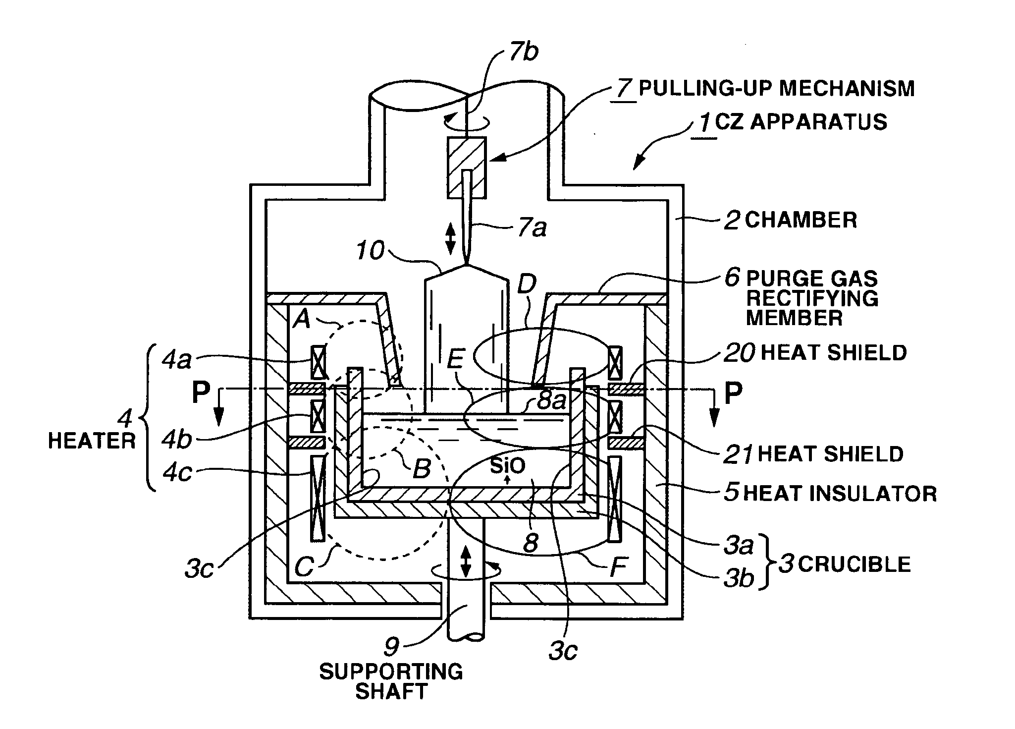
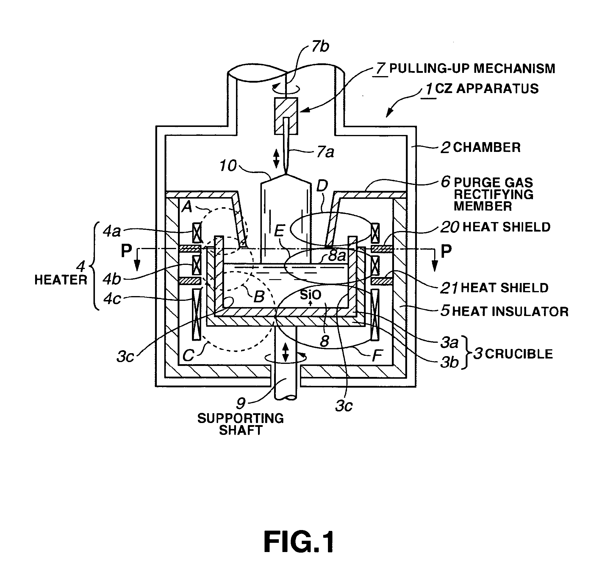
[0070]FIG. 1 is a sectional view of the semiconductor single crystal manufacturing apparatus for illustrating First Embodiment of the present invention.

[0071] CZ apparatus 1 essentially include a crucible 3 disposed in a chamber 2, side heater 4 provided around the outside periphery of the crucible 3, a heat insulator 5 provided around the outside periphery of the side heater 4, a purge gas rectifying member 6 disposed in the vicinity of the crucible 3, and a single crystal pulling-up mechanism 7.

[0072] The crucible 3 is of double structure, including a quartz (SiO2) crucible 3a for pooling silicon melt 8 inside thereof, and a graphite (carbon) crucible 3b which is analogous in shape to the quartz crucible 3a, being fitted thereonto. The melt 8 is in contact with the inside surface of the quartz crucible 3a at a contact surface 3c. In addition, the bottom of the crucible 3 is supported by a supporting shaft 9 which is rotatable and elevatable, whereby the crucible 3 can be rotated...

second embodiment

[0107]FIG. 4 is a conceptual drawing for illustrating another embodiment of the present invention.

[0108] In FIG. 4, a CZ apparatus 1 in Second Embodiment is provided with a structure incorporating a crucible 3, side heater 4 (an upper heater 4a, an intermediate heater 4b, and a lower heater 4c), a heat insulator 5, and the like, in the inside of a chamber 2. As with the CZ apparatus 1 in First Embodiment, and for the components common to those in FIG. 1, the same numerals are provided. Hereinbelow, explanation of them is omitted, and the components other than them will be described in detail.

[0109] In a case of Second Embodiment, a heat shield 22 is provided at a place in the vicinity of a gap between the heater 4a and the heater 4b which are vertically adjacent to each other, and where the heat shield 22 suppresses the mutual thermal interference between the adjacent heaters, and localizes the heating regions for the adjacent heaters. Likewise, a heat shield 23 is provided at a p...

third embodiment

[0113]FIG. 5 is a conceptual drawing for illustrating still another embodiment of the present invention.

[0114] A CZ apparatus 1 in Third Embodiment is provided with a structure incorporating a crucible 3, side heater 4 (an upper heater 4a, an intermediate heater 4b, and a lower heater 4c), a heat insulator 5, and the like, in the inside of a chamber 2, as with the CZ apparatus 1 in First Embodiment. And for the components common to those in FIG. 1, the same numerals are provided. Hereinbelow, explanation of them is omitted, and the components other than them will be described in detail.

[0115] In a case of Third Embodiment, a bottom heater 14 is provided together with a side heater at a place under the lower heater 4c around a supporting shaft 9 in concentricity therewith. In addition, together with heat shields 20, 21, which have been explained in First Embodiment, a heat shield 24 is provided in a gap between the lower heater 4c and the bottom heater 14.

[0116] The bottom heater ...


PUM

PropertyMeasurementUnit
yield rateaaaaaaaaaa
electric poweraaaaaaaaaa
resistanceaaaaaaaaaa

Abstract

A semiconductor single crystal manufacturing apparatus which can manufacture a single crystal of high oxygen concentration to that of low oxygen concentration within a prescribed standard range of oxygen concentration, as a wafer material for semiconductor integrated circuits, with a high yield, is provided. Heat shields 20, 21 are provided in the entire annular area between respective adjacent heaters of the heaters 4a, 4b, 4c for heating the crucible 3 from the outside periphery side. By using the heat shields 20, 21 for localizing the respective heating regions for the heaters to actively control the temperature distribution for the crucible 3 and melt 8 in the crucible, a single crystal of high oxygen concentration to that of low oxygen concentration can be manufactured within a prescribed standard range of oxygen concentration with a high yield.

Description

TECHNICAL FIELD [0001] The present invention relates to a semiconductor single crystal manufacturing apparatus for a silicon single crystal or the like, which provides a material for a semiconductor wafer, and particularly, relates to the semiconductor single crystal manufacturing apparatus using a Czochralski method. BACKGROUND ART [0002] For semiconductor integrated circuits, a silicon wafer having a prescribed oxygen concentration is required to provide a protection against heavy metal contamination or to improve the various types of quality and the yield, and the silicon single crystal, which is a material for such a silicon wafer, can be manufactured with a single crystal manufacturing apparatus using the Czochralski method (hereinafter referred to as CZ apparatus). [0003] With this CZ apparatus, a raw material for single crystal is filled into a crucible disposed inside a chamber, and inert purge gas is introduced into the chamber, while this raw material is heated and melted ...

Claims


Application Information

Patent Timeline
Patent Type & Authority Applications(United States)
IPC IPC(8): C30B29/06C30B15/14
CPCC30B15/14C30B29/06Y10T117/1068Y10T117/1072Y10T117/1088Y10T117/1076C30B15/10
Inventor IIDA, TETSUHIRONODA, AKIKOTOMIOKA, JUNSUKE
Owner SUMCO TECHXIV
Why Eureka
Try Eureka