Spirofluorene derivative, material for light-emitting element, light-emitting element, light-emitting device, and electronic device

a technology of fluorene and derivative, applied in the field of new materials, can solve the problems of large energy gap and few reports, and achieve the effects of high heat resistance, high light-emitting efficiency, and high heat resistan

Active Publication Date: 2007-09-20
SEMICON ENERGY LAB CO LTD
View PDF8 Cites 76 Cited by
  • Summary
  • Abstract
  • Description
  • Claims
  • Application Information

AI Technical Summary

Benefits of technology

[0041] A light-emitting element of the present invention is a light-emitting element having high heat resistance, and also a light-emitting element having high light-emitting efficiency.
[0042] A light-emitting device of the present invention is a light-emitting de

Problems solved by technology

However, few reports have been made on a material having a favorable hole transportin

Method used


Image

  • Spirofluorene derivative, material for light-emitting element, light-emitting element, light-emitting device, and electronic device
  • Spirofluorene derivative, material for light-emitting element, light-emitting element, light-emitting device, and electronic device
  • Spirofluorene derivative, material for light-emitting element, light-emitting element, light-emitting device, and electronic device

Examples


embodiment mode 1

[0097] Embodiment Mode 1 will describe spirofluorene derivatives of the present invention.

[0098] A spirofluorene derivative of the present invention is shown in General Formula 1.

[0099] In the formula, R1 is any one of hydrogen, an alkyl group having 1 to 4 carbon atoms, or a group represented by General Formula 2. As the alkyl group having 1 to 4 carbon atoms, specifically, a methyl group, an ethyl group, an n-propyl group, an iso-propyl group, an n-butyl group, an iso-butyl group, a sec-butyl group, a t-butyl group, or the like can be used. As R1, any one of hydrogen, a t-butyl group, or a group represented by General Formula 2 is particularly preferable.

[0100] In the formula, each of R2 and R3 is either hydrogen or an alkyl group having 1 to 4 carbon atoms. As the alkyl group having 1 to 4 carbon atoms, specifically, a methyl group, an ethyl group, an n-propyl group, an iso-propyl group, an n-butyl group, an iso-butyl group, a sec-butyl group, a t-butyl group, or the like ca...

embodiment mode 2

[0156] Embodiment Mode 2 will describe a light-emitting element which uses a spirofluorene derivative described in Embodiment Mode 1.

[0157] A structure of a light-emitting element in the present invention is such that a layer containing an organic compound is interposed between a pair of electrodes. Note that the element structure is not particularly limited and can be selected as appropriate in accordance with its purposes.

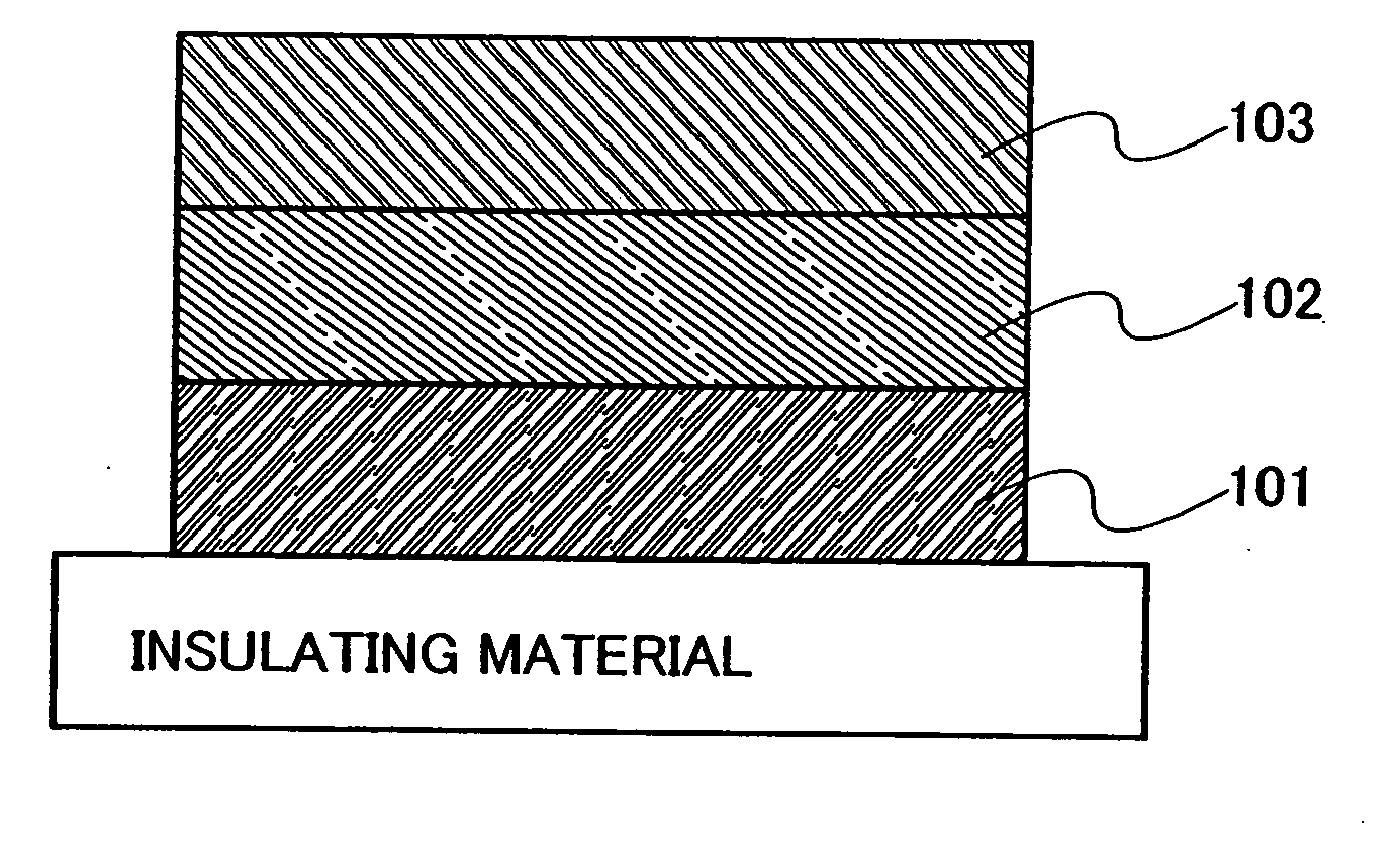
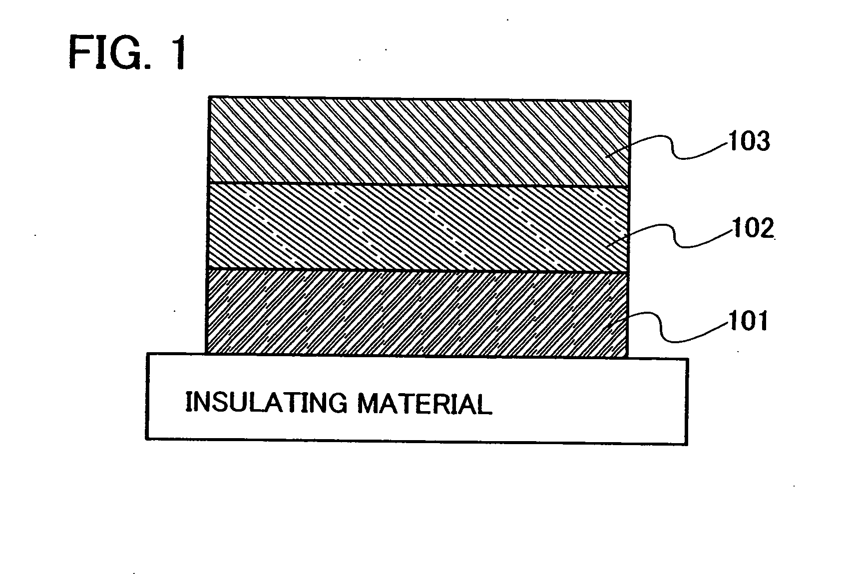
[0158]FIG. 1 schematically shows an example of the element structure of a light-emitting element of the present invention. The light-emitting element shown in FIG. 1 has a structure where a layer containing an organic compound 102 is interposed between a first electrode 101 and a second electrode 103. The layer containing an organic compound 102 contains a compound into which a spirofluorene derivative described in Embodiment Mode 1 is introduced as a substituent. Note that an anode in the present invention refers to an electrode for injecting holes into a laye...

embodiment mode 3

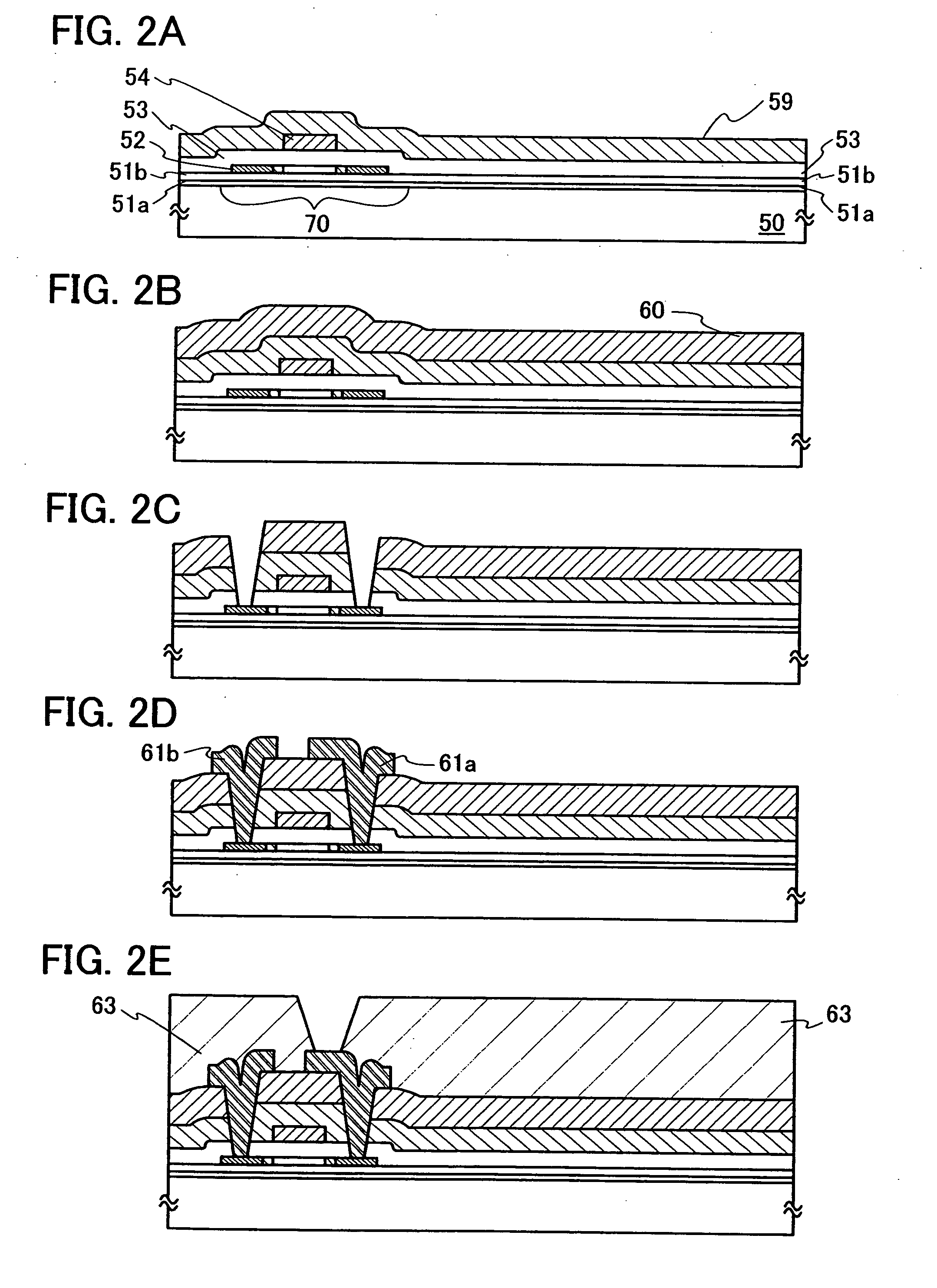
[0176] A light-emitting device of the present invention and a method for manufacturing thereof will be described in this embodiment mode, with reference to FIGS. 2A to 2E and 3A to 3C. Note that an example of manufacturing an active matrix light-emitting device will be described in this embodiment mode; however, the present invention may of course also be applied to a passive matrix light-emitting device.

[0177] First, a first base insulating layer 51a and a second base insulating layer 51b are formed over a substrate 50. Then, a semiconductor layer 52 is formed over the second base insulating layer 51b (FIG. 2A).

[0178] As a material for the substrate 50, glass, quartz, plastic (such as polyimide, acrylic, polyethylene terephthalate, polycarbonate, polyacrylate, or polyether sulfone), or the like can be used. A substrate made from such a material may be used after being polished with CMP or the like, if necessary. In this embodiment mode, a glass substrate is used.

[0179] Providing...


PUM

PropertyMeasurementUnit
Lightaaaaaaaaaa
Energy gapaaaaaaaaaa

Abstract

It is an object of the present invention to provide a material having a high Tg and a wide energy gap. The present invention provides a spirofluorene derivative represented by General Formula 1. (In the formula, R1 is any one of hydrogen, an alkyl group having 1 to 4 carbon atoms, or a group represented by General Formula 2. Each of R2 and R3 is either hydrogen or an alkyl group having 1 to 4 carbon atoms and may be identical or different. R4 is an aryl group having 6 to 15 carbon atoms. Each of R5 and R6 is any one of hydrogen, an alkyl group having 1 to 4 carbon atoms, or an aryl group having 6 to 15 carbon atoms and may be identical or different.)

Description

TECHNICAL FIELD [0001] The present invention relates to a novel material. In particular, the present invention relates to a material which is ideal for use in a light-emitting element in which an organic compound is used in at least one part. In addition, the present invention relates to a light-emitting element, a light-emitting device, and an electronic device which include the material. BACKGROUND ART [0002] A light-emitting device using a light-emitting element which includes a layer containing an organic material between a pair of electrodes and emits light when current flows between the electrodes has been developed. Such a light-emitting device has the advantage of being thin and light, compared with other display devices which are now called thin display devices. Such a device also has high visibility since it is a self light-emitting element, and has a fast response speed. Therefore, this kind of light-emitting device has been actively developed as a next-generation display...

Claims


Application Information

Patent Timeline
IPC IPC(8): H01L29/08
CPCC07C211/61H05B33/14C07D209/86C07D209/88C09K11/06C09K2211/1011C09K2211/1014C09K2211/1022C09K2211/1029H01L51/0058H01L51/006H01L51/0061H01L51/0071H01L51/5012H01L51/5048H01L51/5088C07C2103/94C07C2603/94H10K85/624H10K85/636H10K85/633H10K85/6572H10K50/11H10K50/14H10K50/17Y02E10/549H10K85/626H10K85/657H10K50/82H10K50/818H10K59/123H10K59/1213H10K77/10H10K50/15H10K50/16H10K50/171H10K50/805H10K2102/00H10K2102/103H01L29/4908C07C2603/97
Inventor KAWAKAMI, SACHIKONAKASHIMA, HARUE
Owner SEMICON ENERGY LAB CO LTD
Why Eureka
Try Eureka