Spread illuminating apparatus

a technology of illuminating apparatus and spread light, which is applied in the direction of lighting and heating apparatus, instruments, optical elements, etc., can solve the problems of reducing the luminous efficiency of point light sources, unable to provide a heat radiation system good enough to efficiently release heat generated at point light sources, and raising temperature, etc., to achieve a large section area, improve luminous efficiency, and reduce the effect of radiation

Inactive Publication Date: 2007-09-20
MINEBEA CO LTD
View PDF16 Cites 45 Cited by
  • Summary
  • Abstract
  • Description
  • Claims
  • Application Information

AI Technical Summary

Benefits of technology

[0013]In the aspect of the present invention, the FPC may further include a substrate, with the conductive pattern being composed of first and second conductive patterns formed respectively at the front and rear surfaces of the substrate; the point light source may be mounted on a pair of electrode pads formed at the first conductive pattern; the FPC may have its rear surface affixed to the heat radiating plate; and a heat radiation system from the thermal conductor enclosure to the heat radiating plate may contain a thermal pathway which connects between the thermal conductor enclosure and the second conductive pattern without the substrate intervening therebetween. Thus, the dual conductive pattern structure of the FPC is effectively utilized as a part of the thermal pathway, and the heats emitted from the point light source can be better radiated.
[0014]In the aspect of the present invention, the FPC may include an opening at the front surface thereof so as to expose a part of the second conductive pattern, and the thermal pathway is formed such that the thermal conductor enclosure is connected to the part of the second conductive pattern exposed from the opening. With this structure, the thermal conductor enclosure and the second conductive pattern can be connected to each other directly by a thermal pathway having a relatively small length and a large section area (consequently, rendering a low resistance), thereby further enhancing the heat radiation.
[0015]In the aspect of the present invention, the thermal conductor enclosure may be connected to a thermal pad formed at the first conductive pattern, and the thermal pathway may be formed such that a throughhole communicating with the second conductive pattern is formed at the thermal pad. In this structure, the throughhole enables the thermal pathway to connect between the thermal conductor enclosure and the second conductive pattern directly without the substrate intervening therebetween, and the thermal pads for connection with the thermal conductor enclosure are formed at the first conductive pattern at which the electrode patterns for mounting the point light source are formed, whereby the thermal conductor enclosure can be connected to the conductive pattern easily.
[0016]In the aspect of the present invention, the thermal conductor enclosure may include two separate members opposing each other with an air gap therebetween. In this case, the two separate members of the thermal conductor enclosure may be connected respectively to the pair of electrode pads having each point light source mounted thereon. Since the thermal conductor enclosure composed of two separate members can be brought into a closer and tighter contact with the side faces of the point light source when mounted on the FPC while the two separate members can be electrically insulated from each other surely by the air gap formed therebetween, each of the electrode pads for the point light source and each of the thermal pad for the thermal conductor enclosure can be formed integrally into one single structure, whereby the FPC can be structured simple, and the wiring space of the FPC can be saved.
[0017]In the aspect of the present invention, the thermal conductor enclosure may be made of a copper material and connected to the conductive patter by soldering. In this case, the thermal conductor enclosure may be connected to the conductive pattern when the point light source is mounted on the FPC. Brass as an example of copper material is high in thermal conductance, low in cost, and good in workability, and therefore is a suitable material for a thermal conductor enclosure of the present invention. Also, the thermal conductor enclosure made of brass can be suitably connected to the conductive pattern by soldering, which enables the thermal conductor enclosure to be duly connected to the conductive pattern at the same time the point light source is mounted on the FPC, whereby a good assembling workability can be established. And, since the thermal conductor enclosure is connected to the conductive pattern via solder layer having a high thermal conductance, the heat radiation performance can be enhanced.
[0018]Accordingly, the present invention provides a spread illuminating apparatus, in which the conductive pattern of the FPC is effectively used as a part of the thermal pathway, and the heat emitted from the point light source can be efficiently released from the side surface. Consequently, the spread illuminating apparatus can emit light with a higher intensity while its dimension and profile are kept small. The heat radiation system or structure established in the spread illuminating apparatus according to the present invention can be preferably used, especially, in a spread illuminating apparatus incorporating an LED to which a large current is applied.

Problems solved by technology

The increased current applied to the point light source, however, causes an increase of heat thus raising temperature, which lowers the luminous efficiency of the point light source.
The structure shown in FIG. 9, with lack of a direct heat radiating area, fails to provide a heat radiation system good enough to efficiently release heats generated at point light sources such as LEDs.
Especially, when a large current is applied to the LEDs, heat radiation amount from the LEDs is caused to increase, thus making the problem prominent.
An alternative method to efficiently release the heats generated at the LEDs may be constituted by use of a metallic board of aluminum or copper, but such a metallic board gives restrictions to designing of wirings, patterns, and outer configurations, and also makes it difficult to reduce the height of the spread illuminating apparatus.

Method used


Image

  • Spread illuminating apparatus
  • Spread illuminating apparatus
  • Spread illuminating apparatus

Examples


first embodiment

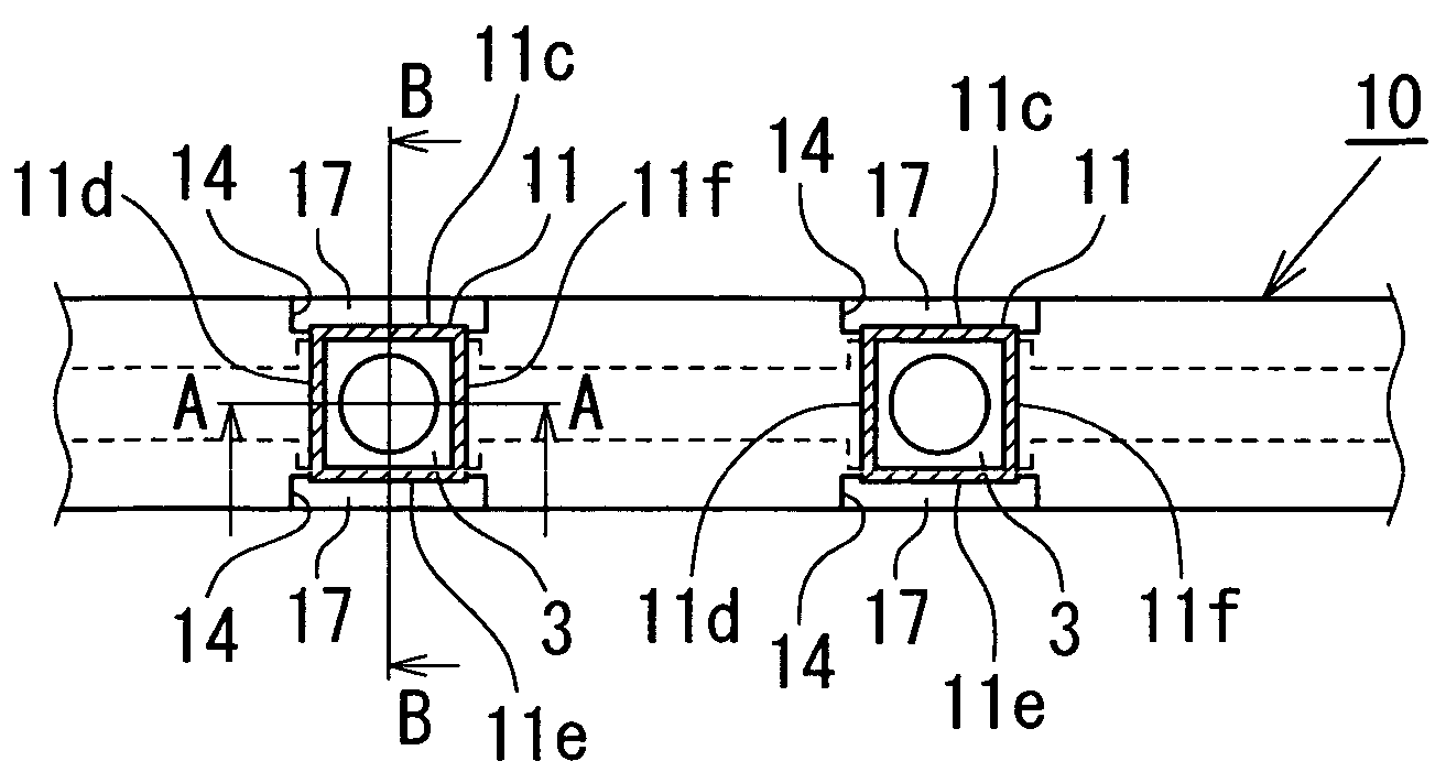
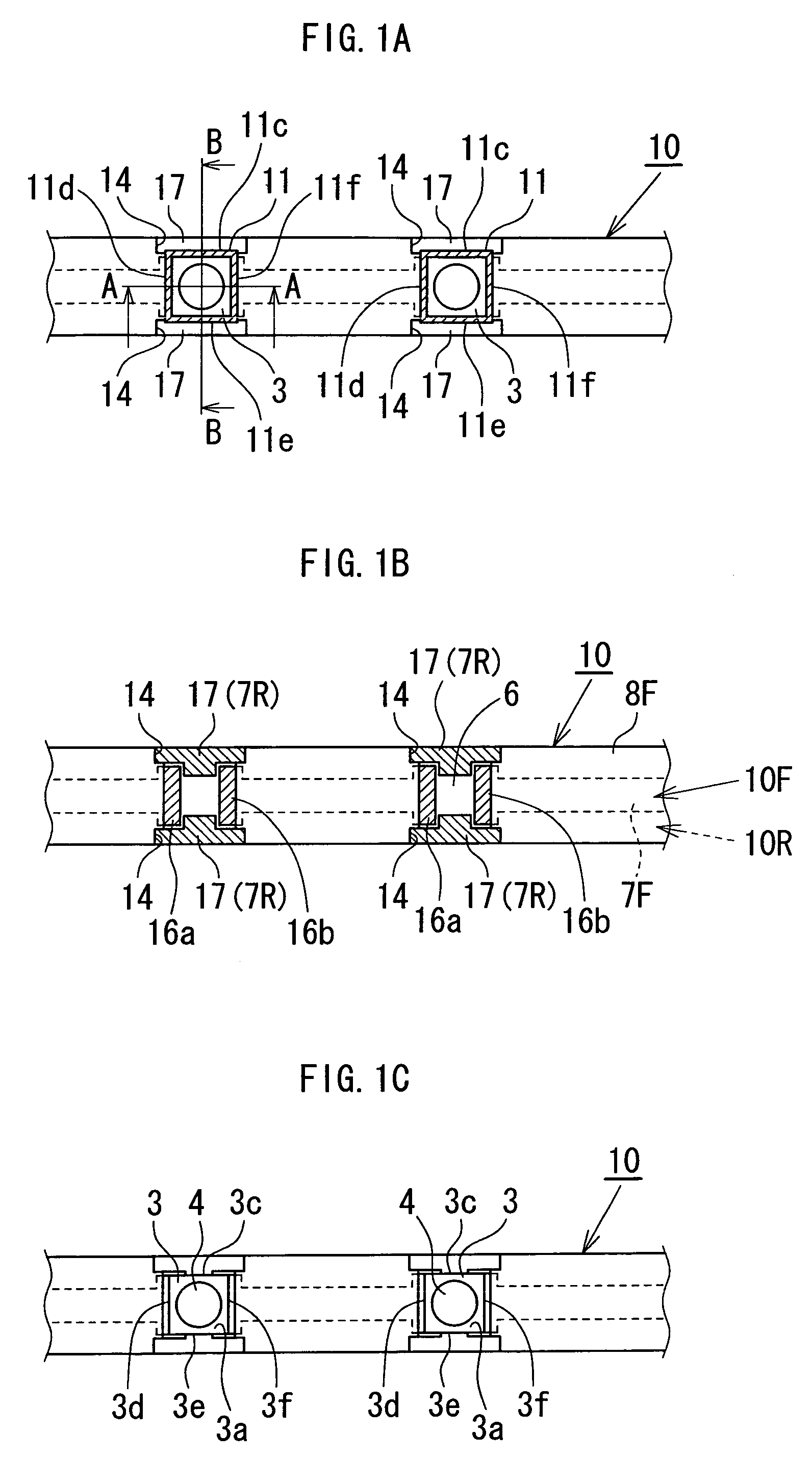
[0029]the present invention will be described with reference to FIGS. 1A to 1C through FIGS. 3A and 3B. A spread illuminating apparatus according to the first embodiment includes a double-sided flexible printed circuit board (hereinafter, referred to as FPC) 10, which, as shown in FIGS. 1B, 3A and 3B, includes a base film (substrate) 6 made of polyimide or like substance, first and second conductive patterns 7F and 7R disposed on respective surfaces of the base film 6 and each formed of a copper foil patterned, and cover films 8F and 8R made of polyimide or the like and disposed so as to cover the first and second conductive patterns 7F and 7R, respectively.

[0030]A pair of electrode pads 16a and 16b on which an LED 3 as point light source is mounted are formed on the first conductive pattern 7F disposed at a front surface 10F of the FPC 10. Openings 14 and 14 are formed at prescribed portions (to be described) of the base film 6 of the FPC 10, and the second conductive pattern 7R di...

second embodiment

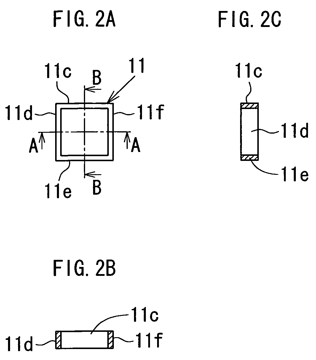
[0044]In the spread illuminating apparatus described above, heat generated at each of the LEDs 3 and emitted from side faces 3c, 3d, 3e and 3f of the LED 3 is caused to be conducted to a heat radiating plate 5, thereby improving the performance of radiating heats generated at point light sources. Since the heat radiation system from the thermal conductor enclosure 11 to the heat radiating plate 5 contains a thermal pathway formed such that the thermal conductor enclosure 11 and the second conductive pattern 7R are connected via the throughholes 21 to each other without a base film 6 of the FPC 30 intervening therebetween, the heats emitted from the LEDs 3 can be efficiently conducted to the heat radiating plate 5 thereby achieving an effective heat radiation.

[0045]An assembly structure indicated by numeral 40 in FIGS. 5A and 5B is preferably manufactured in the same way as the assembly structure indicated by numeral 20 (refer to FIGS. 3A and 3B) explained in the description of the ...


PUM


Abstract

A spread illuminating apparatus includes: a light conductor plate; at least one LED disposed at a side surface of the light conductor plate; an FPC including a substrate and first and second conductive patterns formed respectively at the front ad rear surfaces of the substrate; and a heat radiating plate to hold the FPC. The LED is mounted on electrode pads formed at the first conductive pattern of the FPC, and all the side faces of the LED are covered with an individual thermal conductor enclosure which is connected to the second conductive pattern via an opening formed at the substrate of the FPC. Thus, a heat radiation system is established from the side faces of the LED through to the heat radiating plate which is affixed to the rear surface of the FPC.

Description

BACKGROUND OF THE INVENTION[0001]1. Field of the Invention[0002]The present invention relates to a side light type spread illuminating apparatus, and particularly to a spread illuminating apparatus for use as a lighting means for a crystal liquid display device.[0003]2. Description of the Related Art[0004]A side light type spread illuminating apparatus, in which a primary light source is disposed at a side surface of a light conductor plate, is predominately used as a lighting means for a liquid crystal display (LCD) device used in a mobile telephone, and the like. Conventionally, the primary light source has been constituted by a cold cathode lamp. Currently, a point light source, such as a white light emitting diode (LED), which is easier to handle, enables easier downsizing, and which is more resistant to impact shock than the cold cathode lamp, is heavily used. The application of a spread illuminating apparatus using such a point light source is expanding beyond usage in a small...

Claims


Application Information

Patent Timeline
Patent Type & Authority Applications(United States)
IPC IPC(8): F21V29/00H01L33/62H01L33/64
CPCG02B6/0085G02B6/0083
Inventor SATO, MAKOTO
Owner MINEBEA CO LTD
Why Eureka
Try Eureka