Deferential Presssure Control Method for Molten Carbonates Fuel Cell Power Plants

a technology of molten carbonate and presssure control, which is applied in the direction of fuel cell auxiliaries, fuel cells, fused electrolyte fuel cells, etc., can solve the problems of reducing the efficiency and life expectancy reducing the efficiency of the fuel cell, and the design of the fuel cell system is quite complex and can vary significantly. , to achieve the effect of avoiding an excessive differential pressure, ensuring dynamic pressure balance, and substantially reducing costs

a technology of molten carbonate and presssure control, which is applied in the direction of fuel cell auxiliaries, fuel cells, fused electrolyte fuel cells, etc., can solve the problems of reducing the efficiency and life expectancy reducing the efficiency of the fuel cell, and the design of the fuel cell system is quite complex and can vary significantly. , to achieve the effect of avoiding an excessive differential pressure, ensuring dynamic pressure balance, and substantially reducing costs

US20070224467A1Inactive Publication Date: 2007-09-27ANSALDO FUEL CELLS SPA

Image

  • Deferential Presssure Control Method for Molten Carbonates Fuel Cell Power Plants
  • Deferential Presssure Control Method for Molten Carbonates Fuel Cell Power Plants
  • Deferential Presssure Control Method for Molten Carbonates Fuel Cell Power Plants

Examples


Embodiment Construction

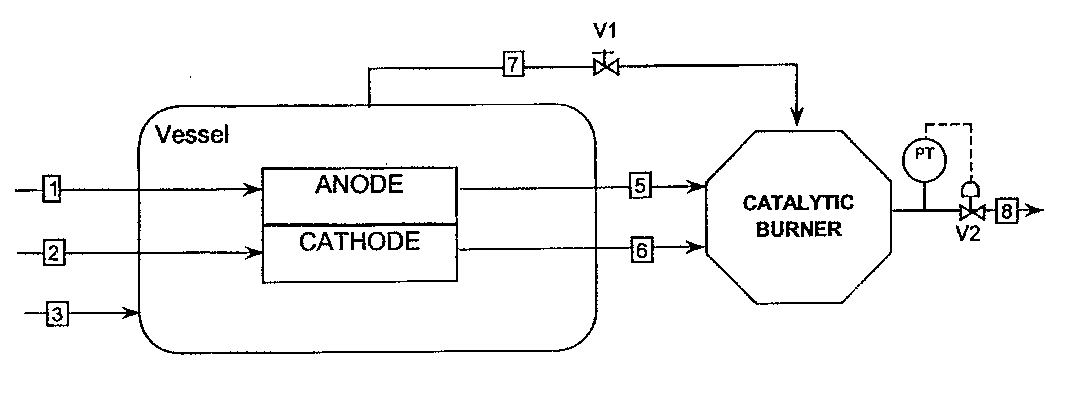
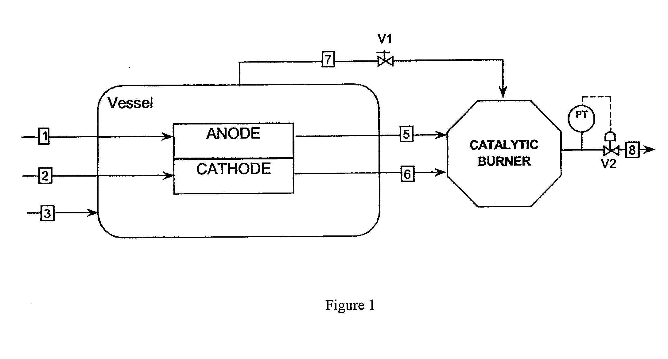
[0037] The preferred embodiments of the present invention will be described with reference to FIG. 1.

[0038] A pressurised fuel feed line 1 is connected to the anode of the fuel cell stack. A pressurised oxidant feed line 2 is introduced into the cathode and inert gas (N2) air or other mixtures like cathodic exhaust is fed to the containment vessel through line 3.

[0039] The system pressure is controlled by the valve V2 downstream of the catalytic burner, the pressure sensor and pressure controller.

[0040] Valve V1, located on the vessel exhaust line, maintains constant the required differential pressure between the vessel and the fuel cell reactants in order to prevent leakage of reactants to the vessel atmosphere.

[0041] In this case, the anode, the cathode and the vessel exits are all at the same pressure, which is balanced and equilibrated inside the catalytic burner that acts as reference point. Anode and cathode pressures are always equilibrated unless pressure drop occurs in ...


PUM

PropertyMeasurementUnit
temperatureaaaaaaaaaa
pressureaaaaaaaaaa
differential pressureaaaaaaaaaa

Abstract

A molten carbonate fuel cell System in which the fuel cell stack(s) is (are) enclosed within a containment vessel and in which a burner exhaust is used to control the system operating pressure is described. Moreover, highly reliable, simple and low-cost differential pressure control method never affected by service interruption or troubles in control valves or other components is disclosed. Excluding differential control valves and reducing the cost by guiding the anode, cathode and vessel exhaust gases to the inlet of a catalytic burner forward the containment vessel and mixed therein so that the pressure of these gases are equal to each other, this fuel cell system guarantees dynamic pressure balancing between the vessel and reactants to prevent leakage of the reactants from the fuel cell stack and avoid an excessive differential pressure between the fuel cell and the vessel and between the anode and the cathode.

Description

[0001] At the cathode, oxygen combines with electrons and, in some cases, with species such as protons or water, resulting in water or hydroxide ions, respectively. [0002] For polymer exchange membrane (PEM) and phosphoric acid fuel cells, protons move through the electrolyte to the cathode to combine with oxygen and electrons, producing water and heat. [0003] For alkaline, molten carbonate, and solid oxide fuel cells, negative ions travel through the electrolyte to the anode where they combine with hydrogen to generate water and electrons. The electrons from the anode side of the cell cannot pass through the membrane to the positively charged cathode; they must travel around it via an electrical circuit to reach the other side of the cell. This movement of electrons is an electrical current. [0004] The amount of power produced by a fuel cell depends upon several factors, such as fuel cell type, cell size, the temperature at which it operates, and the pressure at which the gases are...

Claims


Application Information

Patent Timeline
27 Sep 2007
Publication
US20070224467A1
IPC
H01M8/14; H01M8/04; H01M8/06; H01M8/24
CPC
H01M8/04104; H01M8/0662; Y02E60/526; H01M2008/147; Y02E60/50; H01M8/244; H01M8/2457
Inventors
NERVI, GIAN PAOLO; PARODI, FILIPPO