
Light emitting device

a technology of light emitting device and sealing material, which is applied in the direction of semiconductor devices, electrical equipment, basic electric elements, etc., can solve the problems of reducing the reflection coefficient, affecting replacing the sealing material from the epoxy resin to the silicone based resin, etc., to enhance the long-term reliability of the light emitting device, prevent discoloration, and stabilize the bond

Inactive Publication Date: 2007-10-04
TOYODA GOSEI CO LTD
View PDF7 Cites 25 Cited by
  • Summary
  • Abstract
  • Description
  • Claims
  • Application Information

AI Technical Summary

Benefits of technology

[0024] (vii) The organic compound comprises at least one of benzotriazole compound, triazole compound, thiocyanic acid based compound, silane compound, titanium compound, triazine compound, benzoimidazole compound, imidazole compound, compound containing mercaptocarboxylic acid and / or salts thereof, thiazole compound, benzothiazole compound, thionalide, oxazole compound, and thiol compound.
[0025] (viii) The silicone-based resin material comprises a phosphor that allows the device to emit a white light.
[0026] By the invention, the protecting layer can have a stable bond to the light reflecting layer, and can keep its discoloration preventing effect for the light reflecting layer even under high heat load to enhance the long-term reliability of the light emitting device.

Problems solved by technology

However, in the light reflecting layer formed of metal, there is a disadvantage that the reflection coefficient may be decreased when the light reflecting layer is discolored due to heat or gas penetrating through the sealing material.
Based on the above differences, there are many problems in replacing the sealing material from the epoxy resin to the silicone based resin materials.
In case of using the silicone based resin materials as the sealing material, it has been recently pointed out as a problem that the long-term reliability becomes difficult to keep due to the significant discoloration (i.e., decrease in reflection coefficient) of the light reflecting layer.
Of them, Ag is particularly subject to deterioration.

Method used


Image

  • Light emitting device
  • Light emitting device
  • Light emitting device

Examples


first embodiment

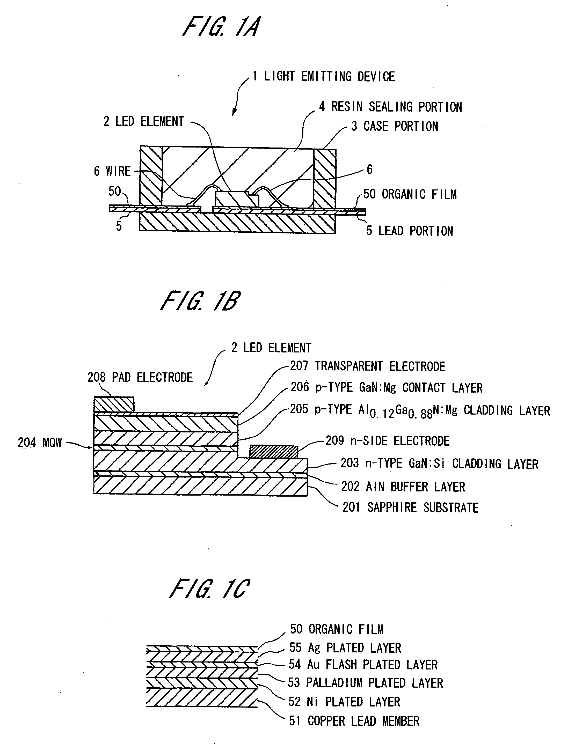
[0033]FIG. 1A is a longitudinal cross sectional view showing a light emitting device of surface-mounted type in a first preferred embodiment according to the invention, FIG. 1B is a longitudinal cross sectional view showing a light emitting element, and FIG. 1C is an enlarged cross sectional view showing a lead portion in FIG. 1A.

[0034] The light emitting device 1 comprises a LED element 2 formed on a sapphire substrate by a crystal growth of a GaN-based semiconductor layer, a case portion 3 formed of white resin or ceramics comprising a light reflectivity, a resin sealing portion 4 sealing an opening portion of the case portion 3 housing the LED element 2, a lead portion 5 for feeding electrical power to the LED element 2 housed in the case portion 3, the lead portion 5 comprising a Ag plated layer as a light reflecting layer formed on the surface thereof and an organic film 50 formed of organic compounds and formed on the surface of the light reflecting layer as a protecting laye...

second embodiment

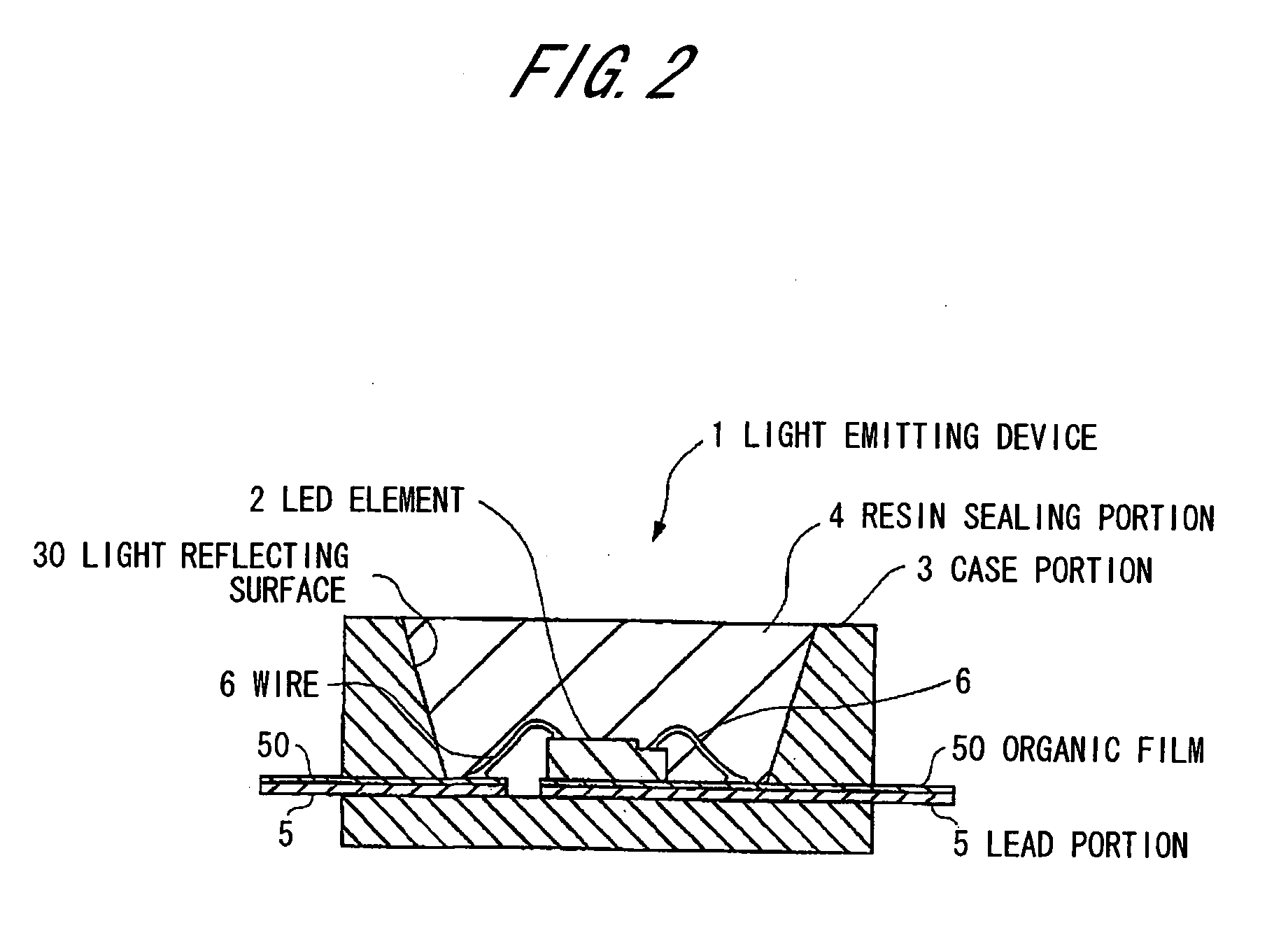
[0046] FIG.2 is a longitudinal cross sectional view showing a light emitting device of surface-mounted type in a second preferred embodiment according to the invention.

[0047] The light emitting device 1 in the second preferred embodiment is different from the device of the first preferred embodiment in that the device 1 comprises a light reflecting surface 30 inclined to the inside of the case portion 3, so as to enhance an outward taking out efficiency by reflecting the light emitted from the LED element 2 and entering the light reflecting surface 30 in the direction based on the inclined angle.

[0048] Further, a light reflective film comprising light reflective materials such as aluminum (Al) can be formed on the light reflecting surface 30.

Advantages of the Second Embodiment

[0049] According to the second preferred embodiment of the invention described above, in addition to the preferred advantages of the first preferred embodiment, the blue light emitted from the LED element 2...

third embodiment

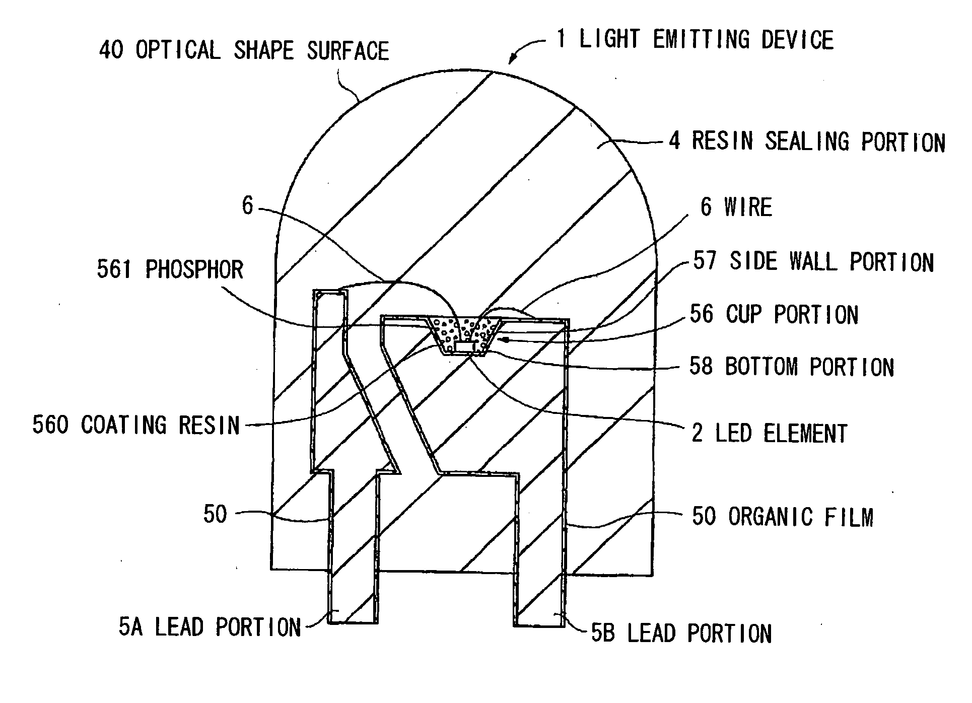
[0050] FIG.3 is a longitudinal cross sectional view showing a light emitting device of bullet type in a third preferred embodiment according to the invention.

[0051] The light emitting device 1 in the third preferred embodiment comprises lead portions 5A, 5B comprising copper alloy superior to thermal conductivity, the LED element 2 to emit a blue light, being fixed in a cup portion 56 formed on the lead portion 5B by impression process, a wire 6 electrically connecting electrodes of the LED element 2 and the lead portions 5A, 5B, a coating resin 560 comprising silicone containing a phosphor 561 to emit a yellow light when excited by a blue light, and sealing the cup portion 56 in which the LED element 2 is housed, and a resin sealing portion 4 comprising transparent and colorless epoxy resin, integrally sealing the lead portions 5A, 5B and the wire 6.

[0052] The cup portion 56 comprises the side wall portion 57 formed at a slant so as to reflect the blue light emitted from the LED ...


PUM


Abstract

A light emitting device has an LED (light emitting diode) element, and a power feeding member through which electrical power is fed to the LED element, the power feeding member comprising an electrically conductive material. The power feeding member has a light reflecting layer formed on the surface of the power feeding member, the light reflecting layer being formed of a metal, and a protecting layer formed on the surface of the light reflecting layer, the protecting layer being formed of an organic compound.

Description

[0001] The present application is based on Japanese patent application No. 2006-089944 filed on Mar. 29, 2006, the entire contents of which are incorporated herein by reference. BACKGROUND OF THE INVENTION [0002] 1. Field of the Invention [0003] This invention relates to a light emitting device that is formed of a light emitting diode (LED), and uses as a light reflecting layer a power feeding member through which to feed electrical power to the LED and, in particular, to a light emitting device that, in case of using silicone based materials to seal the power feeding member, can prevent discoloration of the light reflecting layer to enhance the long-term reliability of the light emitting device. [0004] 2. Description of the Related Art [0005] Conventionally, a light emitting element formed of gallium nitride (GaN) is known as one of group III nitride-based compound semiconductor light emitting elements. Since the GaN type light emitting element has a light emitting property to emit...

Claims


Application Information

Patent Timeline
Patent Type & Authority Applications(United States)
IPC IPC(8): H01L33/00H01L33/60H01L33/06H01L33/32H01L33/42H01L33/50H01L33/54H01L33/56H01L33/62
CPCH01L33/46H01L33/62H01L2224/48091H01L2224/48247H01L2224/49107H01L2224/73265H01L2224/32245H01L2924/01046H01L2924/01057H01L2924/01078H01L2924/01079H01L2224/48257H01L2924/01012H01L2924/00014H01L2924/00H01L2924/12044
Inventor MINAMI, YUKIMURAISHIDA, MAKOTO
Owner TOYODA GOSEI CO LTD
Learn More