Method and apparatus for recycling process fluids

a technology of process fluid and recycling method, which is applied in the direction of mechanical equipment, water supply installation, transportation and packaging, etc., can solve the problems of thinning of the interconnection, new manufacturing challenges, and complex process steps involved in the manufacture of semiconductor devices, and achieve the effect of preventing electromigration

a technology of process fluid and recycling method, which is applied in the direction of mechanical equipment, water supply installation, transportation and packaging, etc., can solve the problems of thinning of the interconnection, new manufacturing challenges, and complex process steps involved in the manufacture of semiconductor devices, and achieve the effect of preventing electromigration

US20070235392A1Active Publication Date: 2007-10-11AIR LIQUIDE ELECTRONICS US LP

Image

  • Method and apparatus for recycling process fluids
  • Method and apparatus for recycling process fluids
  • Method and apparatus for recycling process fluids

Examples


Embodiment Construction

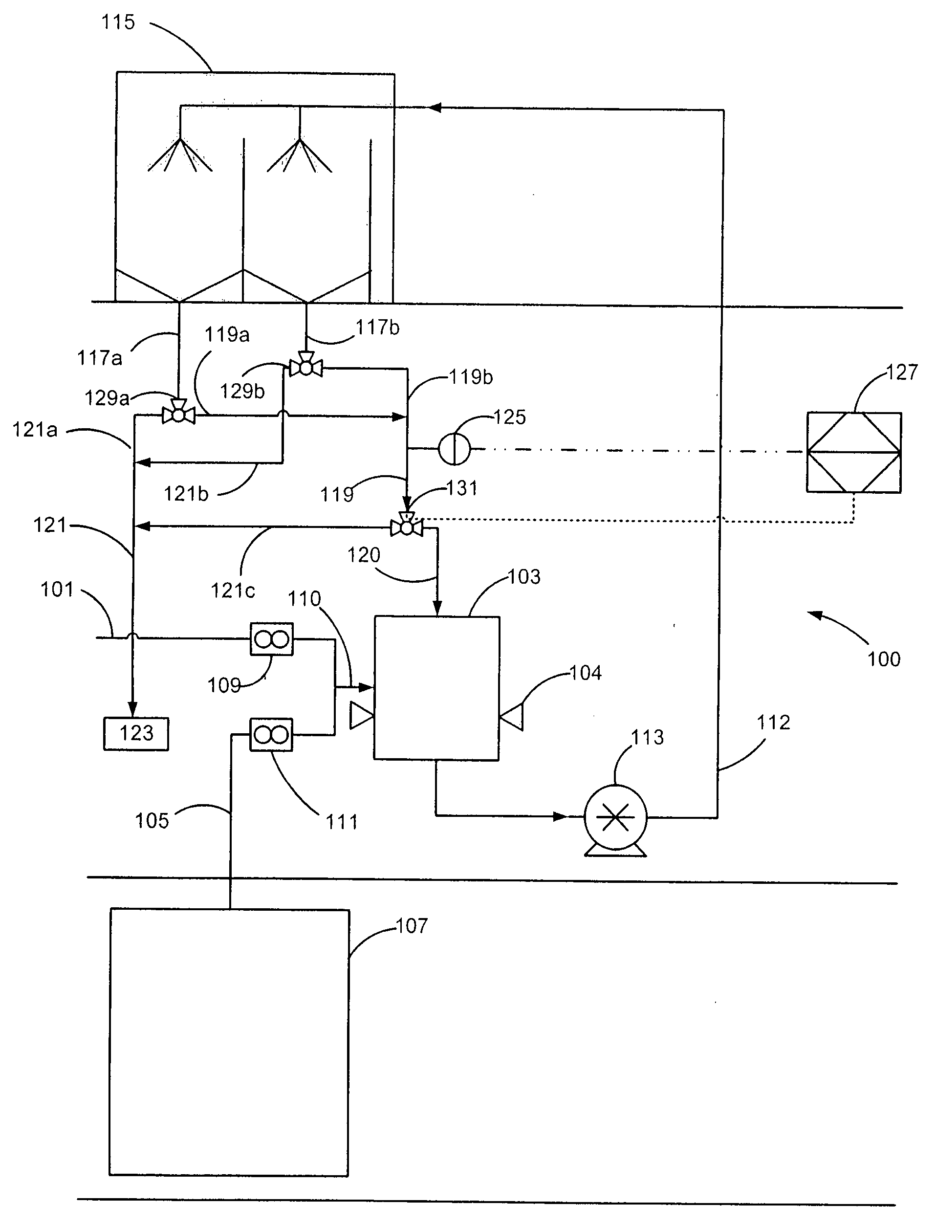
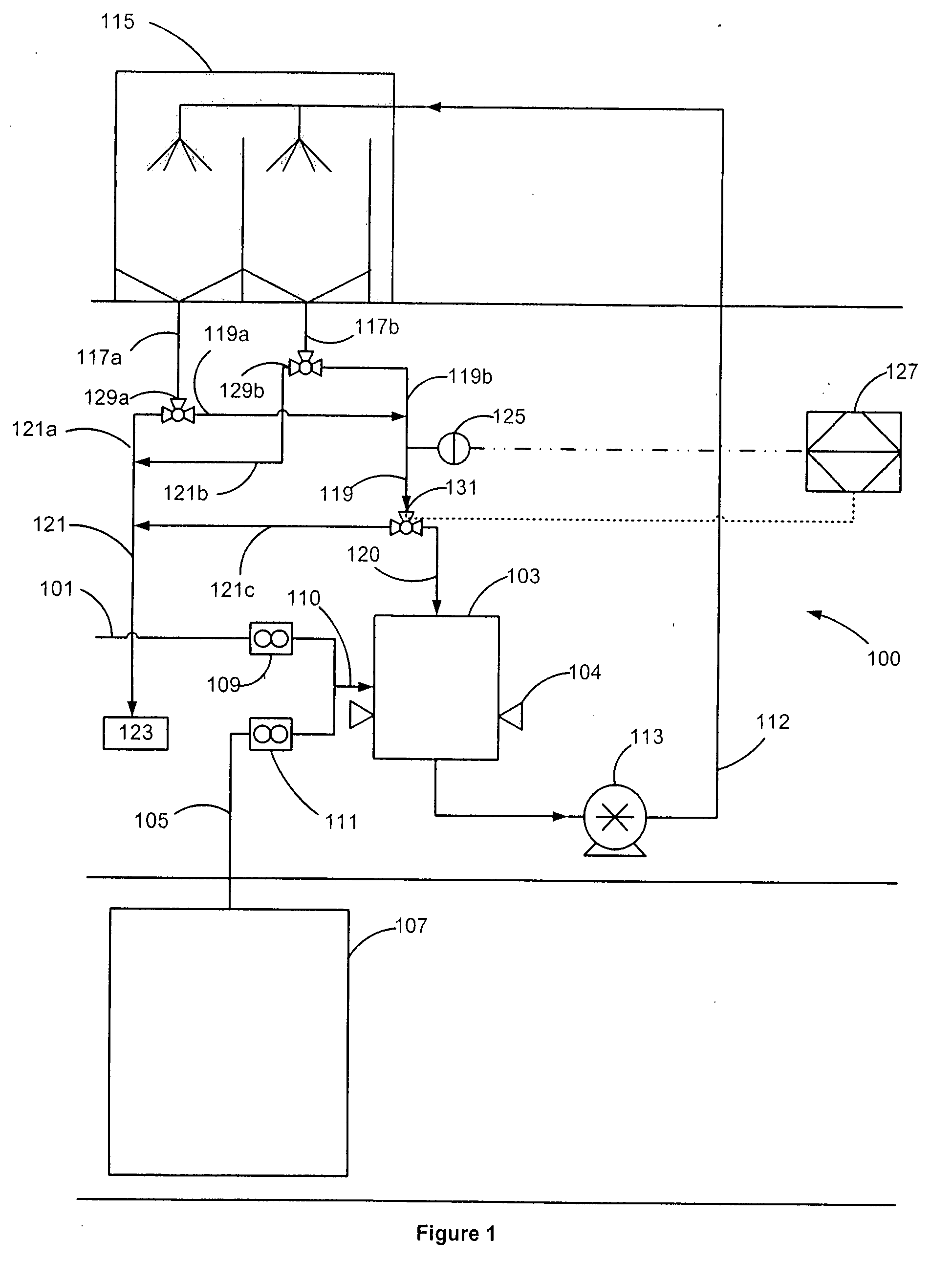
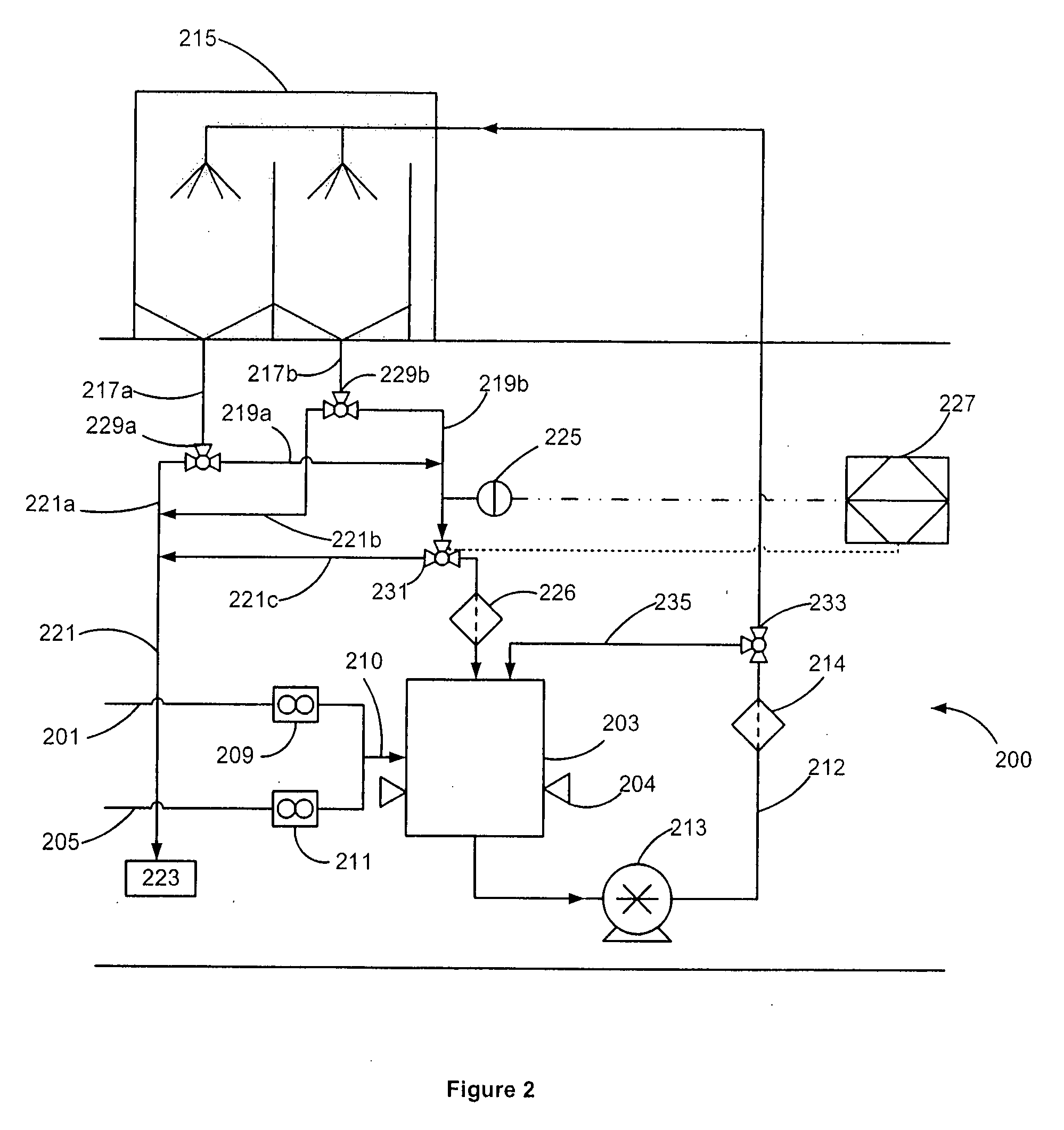
[0012] Embodiments of the present invention are shown in FIGS. 1 and 2. The invention is directed to a system for recycling a used process fluid reclaimed from a drain of a semiconductor process tool. The reclaimed process fluid is either recycled back to an inlet of the process tool if a condition of the used process fluid is within a predetermined range or drained from the system. In one embodiment, the invention provides a blending and distribution and recycle and reclaim system that supplies used process fluid to a point of use (e.g. a semiconductor process tool). More specifically, the invention provides an apparatus and method for blending at least two fluids to form a semiconductor process fluid, distributing the mixture to a semiconductor process tool at a sufficient pressure for semiconductor processing, reclaiming the mixture and, based upon certain parameters, either recycling or draining the mixture.

[0013]FIG. 1 shows an embodiment of the recycling system 100 according ...


PUM

PropertyMeasurementUnit
pressureaaaaaaaaaa
flow rateaaaaaaaaaa
flow rateaaaaaaaaaa

Abstract

A method and apparatus for recycling a process fluid from a drain of a semiconductor process tool. The process fluid may be an acidic cobalt solution or an electroless cobalt solution used in a semiconductor process step to prevent electromigration in copper interconnects. The used process fluid is collected from the tool drain and recycled back to the tool inlet if a condition of the fluid is within a predetermined range. Otherwise, the used process fluid is drained from the system. The system may also operate in a bleed and feed mode where a portion of the used process fluid is periodically drained from the system.

Description

CROSS-REFERENCE TO RELATED APPLICATION(S) [0001] This application claims priority from U.S. Provisional Patent Application Ser. No. 60 / 789,404 filed Apr. 4, 2006.FIELD OF THE INVENTION [0002] The present invention is directed to a method and apparatus for recycling a process fluid from a semiconductor process tool. More particularly, the invention is directed to a method and apparatus for recycling or draining a used process fluid from a semiconductor process tool based upon a condition of the used process fluid. BACKGROUND OF THE INVENTION [0003] The manufacture of semiconductor devices is a complex process that can involve over 200 process steps. Each step requires optimal conditions to ultimately result in a high yield of semiconductor devices. Many process steps require the use of fluids to inter alia etch, clean, expose, coat, and polish the surface layers of the devices during manufacturing. In high purity fluid applications, the fluids (e.g. hydrofluoric acid, sulfuric acid, ...

Claims


Application Information

Patent Timeline
11 Oct 2007
Publication
US20070235392A1
IPC
C02F1/00
CPC
B01F3/088; B01F15/0408; H01L21/30; B01F2215/0096; C23F1/00; B01F2215/0036; Y10T137/2698; Y10T137/0324
Inventors
EDWARDS, DAVID PAUL