Rolling bearing

a technology of rolling bearings and bearings, which is applied in the direction of bearings, shafts and bearings, rotary bearings, etc., can solve the problems of rolling bearings made of stainless steel, tend to reach the end of life, metal abrasion of rolling bearings,

Inactive Publication Date: 2007-10-18
NTN CORP
View PDF11 Cites 11 Cited by
  • Summary
  • Abstract
  • Description
  • Claims
  • Application Information

AI Technical Summary

Benefits of technology

[0018]According to the present invention, because a solidified lubricating oil obtained by heat-curing a mixture of lubricating oil or grease and a thermoplastic resin or thermosetting resin is sealed in the bearing by contact seals made of fluorine rubber, if the rolling bearing made of stainless steel is used in corrosive use conditions where hydrofluoric acid or fluorine grease is present, metallic corrosion powder will not infiltrate into the rolling surfaces and normal lubricating oil will be kept supplied without being decomposed, thus preventing abnormal wear or rapid progression of internal wear.
[0019]Due to these advantages, the rolling bearing of this invention can work as a long life rolling bearing even if used with a cleaning / chemical polishing apparatus using corrosive fluorides.

Problems solved by technology

The fluoride is a kind of Lewis acid having extremely high corrosivity and acts on PFPE, which is a base oil, as a decomposition catalyst, so that the fluorine lubricating grease will be rapidly decomposed and flow away, thus causing metal abrasion of the rolling bearing.
By such corrosion mechanism, rolling bearings made of stainless steel and having fluorine lubricating grease sealed therein tend to reach the end of life in a short time with rapid progression of internal wear.
Also, even rolling bearings made of stainless steel and not containing fluorine lubricating grease corrode and produce metallic abrasion powder in use conditions in which they are exposed to hydrofluoric acid as a cleaning or polishing agent.
The metal abrasion powder infiltrates into rolling portions of the bearing, causing boundary lubrication and thus abnormal bearing wear.

Method used


Image

  • Rolling bearing
  • Rolling bearing

Examples


example 1

OF THE INVENTION

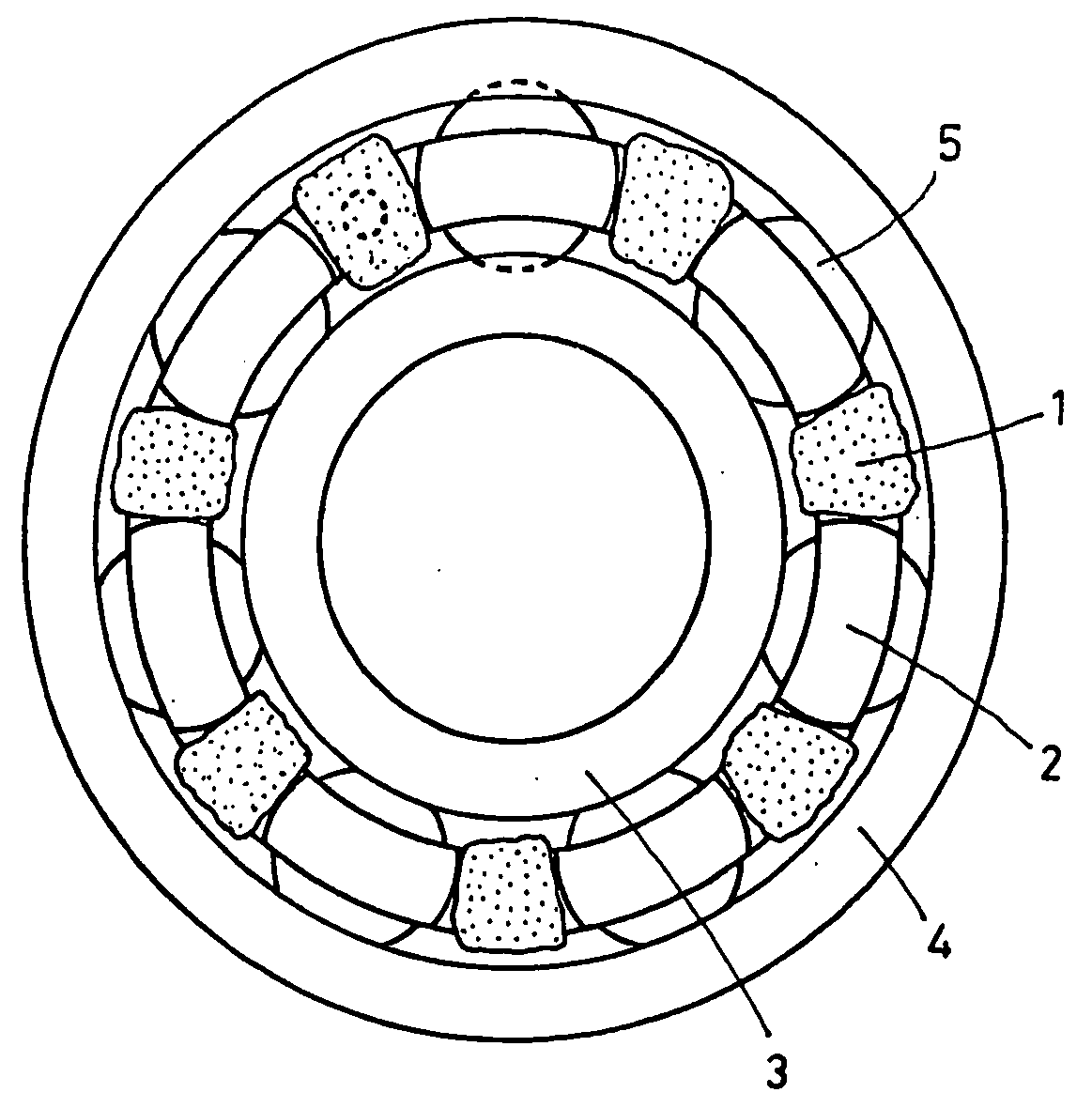
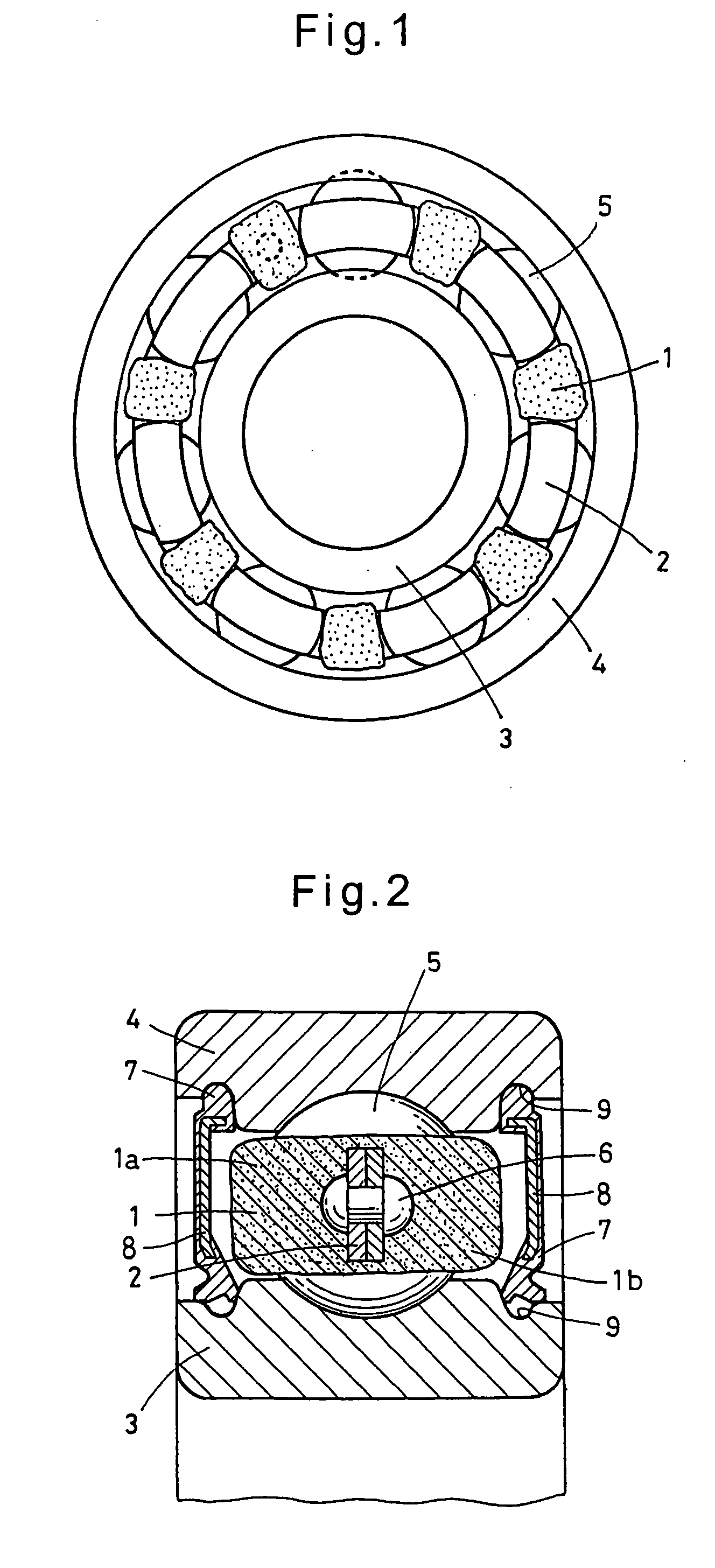
[0043]Deep-groove ball bearings (inner diameter: 10 mm, outer diameter: 26 mm, width: 8 mm) with contact seals as shown in FIGS. 1 and 2 were made as follows: That is, the inner and outer rings were made of stainless steel (SUS440C), the rolling elements were made of silicate nitride ceramics (Si3N4), and the retainer was made of stainless steel (SUS304). For the solidified lubricating oil, lithium-mineral oil grease containing polyethylene resin powder was used. General-purpose Polylube LP03 made by NTN and having a softening temperature of about 80° C. and a curing temperature of about 130° C. was spot packed on both axial sides of the retainer in the bearing, and heat cured. Then, the gap between the outer ring and the inner ring was sealed by contact seals of fluorine rubber. The rolling bearings of this invention were obtained by doing so. The rolling bearings were subjected to the following durability tests under the conditions corresponding to the actual use c...


PUM

PropertyMeasurementUnit
particle sizeaaaaaaaaaa
widthaaaaaaaaaa
outer diameteraaaaaaaaaa

Abstract

A rolling bearing made of stainless steel is provided which in use conditions where hydrofluoric acid or fluorine grease is present, can prevent boundary lubrication due to invasion of metal corrosion powder into rolling surface of the bearing, and rapid advance of internal wear and which is highly durable and has a long life even if used in metal corrosive environments. A deep-groove rolling bearing is proposed which comprises bearing rings (inner ring and outer ring), rolling elements and a retainer all made of stainless steel, and solidified lubricating oil sealed in the rolling bearing. The solidified lubricating oil is made by heat curing a mixture of lubricating oil or grease containing perfluoropolyether and a thermoplastic resin. Contact seals made of fluorine rubber seal the solidified lubricating oil. Even if metal abrasion powder is produced by effect of perfluoropolyether or hydrofluoric acid, it will be held embedded in the solidified lubricating oil, so that abnormal wear will not occur.

Description

BACKGROUND OF THE INVENTION[0001]The present invention relates to rolling bearings, particularly to rolling bearings suitable for use with a cleaning / chemical polishing apparatus used in environments in which they are brought into contact with corrosive fluoride compounds for cleaning and chemical polishing.[0002]Generally, in e.g. wafer cleaning and chemical polishing steps in semiconductor manufacturing facilities, corrosive fluoride compounds such as hydrofluoric acid are used as cleaning agents or surface treatment agents. For example, in a Chemical Mechanical Polishing (CMP) apparatus, wafer surfaces are cleaned and polished by a rotary brush while showering hydrofluoric acid on wafers.[0003]Rolling bearings used in or with the carrying unit and rotary brush of such a cleaning apparatus are made of a corrosion-resistant material. For example, bearing rings, rolling elements and retainers made of stainless steel are adopted (JP patent publication 2003-139147A).[0004]On the other...

Claims


Application Information

Patent Timeline
Patent Type & Authority Applications(United States)
IPC IPC(8): F16C19/00
CPCF16C33/44F16C33/6688F16C33/6633Y10S384/907
Inventor TANAKA, HIDEAKINAKAJIMA, RYOUICHI
Owner NTN CORP
Why Eureka
Try Eureka