
Hydrogen-generating solid fuel cartridge

a solid fuel cartridge and liquid hydrogen technology, applied in the field of liquid hydrogen-generating solid fuel cartridges, can solve the problems of difficult reaction to continue, low deliverable energy density of liquid hydrogen or high-pressure hydrogen gas, stringent storage material requirements, etc., and achieve the effect of reducing the diffusion barrier

Inactive Publication Date: 2007-10-18
INTEMATIX
View PDF11 Cites 25 Cited by
  • Summary
  • Abstract
  • Description
  • Claims
  • Application Information

AI Technical Summary

Benefits of technology

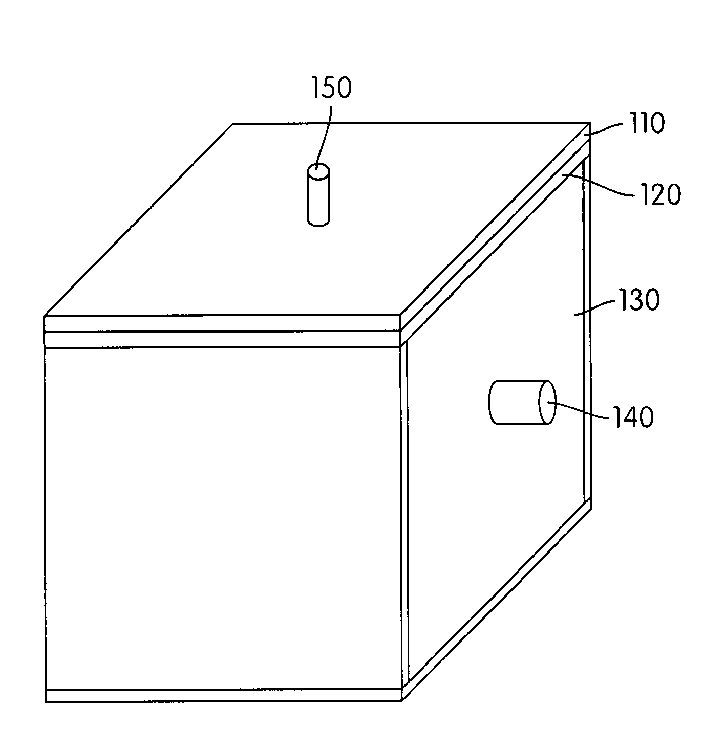
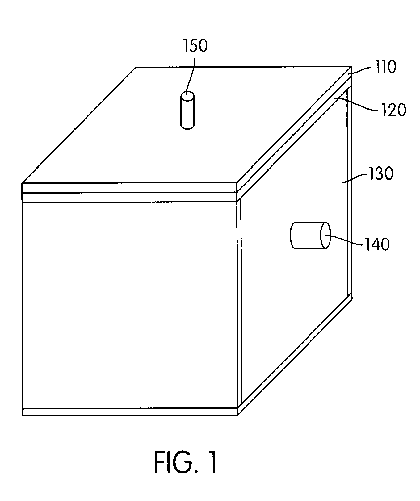
[0019] In another embodiment of the present invention, a gas collecting, hydrophobic (water-based liquid-repelling) material is packed inside the solid reactant cartridge to collect hydrogen that has been generated during the reaction between the solid fuel and the liquid reactant. This material may comprise a network of membranes, and because the membranes are water-repellent and gas permeable, the hydrogen generated within the solid fuel cartridge may diffuse and be transported outside the cartridge. Simultaneously, the hydrophobic nature of the hydrogen-collecting membranes prevents water from exiting the cartridge along with the hydrogen product.
[0021] In another embodiment of the present invention, the solid reactant can be premixed with additives to improve reaction probabilities. Such additives might not be described as a “catalyst,” though, because the additives may participate in the reaction that generates the hydrogen.
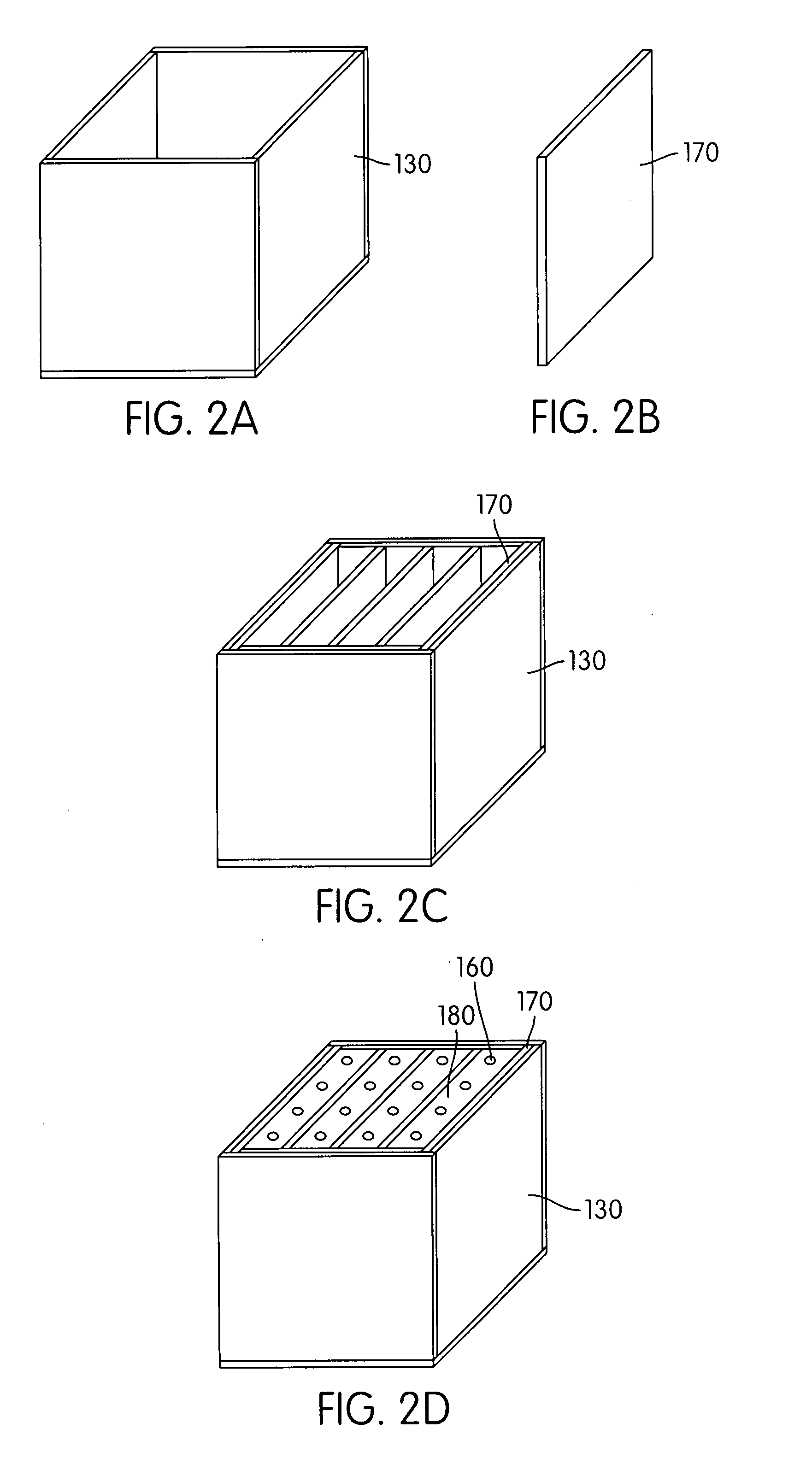
[0022] The means for distributing the liquid reactant throughout the solid fuel / catalyst mixture in the cartridge may be connected with the liquid dispensing plate such that liquid can flow via these means into the bulk of the mixture in predetermined patterns that are not symmetrical or uniform. Any three dimensional pattern may be designed for dissipating the liquid reactant into the surrounding solid fuel. The distribution medium may take a variety of forms; for example, a two-dimensional membrane in flat or sheet form, or a one dimensional hollow tube. In this latter embodiment, the solid fuel reactant may be mixed with fibers having capillary channels. The capillary channels have the ability to wick liquid from one end of a fiber to the other. The fibers may be interconnected inside the solid reactant cartridge, and are in contact with the liquid conducting medium. In this manner, a liquid distribution network is formed inside the solid reactant cartridge, with water acting as the conducting media, and the fibers functioning as local channels for the main channel. Such a network reduces the diffusion barrier for liquid inside the solid reactant package.

Problems solved by technology

Hydrogen can be stored in the form of a high pressure gas or a liquid, but each of these methods requires high pressure operation which imposes stringent requirements for the storage materials.
Furthermore, the deliverable energy density for liquid hydrogen or high pressure hydrogen gas is low.
A disadvantage of this system is that for proper operation, the concentration of sodium borohydride should not be greater than about 25 wt % so that enough water remains after the reaction to dissolve the product NaB(OH)4 that is formed.
If this happens, it is difficult for the reaction to continue.
These disadvantages notwithstanding, the hydrogen storage density is still greater than that described above for the solution based processes.
The disadvantages inherent with the practical application of the capillary approach taught by U.S. Pat. No. 6,746,496 are numerous.
First, the solid hydrogen-fuel source is located on the same substrate as the water reservoir, along with the dispensing channel and flow controlling valve; such that the assembly / module is not readily and / or conveniently disposable.
A second disadvantage is that although water is recycled from the fuel cell, the configuration of this hydrogen generation system does not allow recycled water to reach the sodium borohydride, since there is no channel on the substrate connecting to an external water source.
A third disadvantage is that micron-sized particles of solid hydrogen-source materials are closely-packed in the solid fuel cavity.
To achieve such a design, a restricted particle size of sodium borohydride is required, which makes the manufacturing of sodium borohydride costly.

Method used


Image

  • Hydrogen-generating solid fuel cartridge
  • Hydrogen-generating solid fuel cartridge
  • Hydrogen-generating solid fuel cartridge

Examples


example 1

[0060] The results of the experiment when the hydrogen-generating solid fuel is sodium borohydride NaBH4 and the catalyst is 20 wt % RuCl3 is shown in FIG. 8. There are three curves in the graph. The actual hydrogen generation rate, measured using the mass flow meter, is plotted on the graph. The theoretical hydrogen generation rate, a calculation based on the water delivery rate and equation (1) is also plotted on the graph for comparison. The third curve on the graph is the hydrogen generation rate that would be required to power a typical laptop computer. Although an excess of water was required above that which the fuel cell generated, the results indicate that hydrogen generation rate met the power requirements of the laptop.

example 2

[0061] The results of the experiment when the hydrogen-generating solid fuel is sodium borohydride NaBH4 and the catalyst is 20 wt % CoBr2 is shown in FIG. 9. This experiment was performed in a slightly different manner, in that the water delivery rate to the fuel cell was changed twice (the first time at about 2500 seconds into the experiment; the second time at about 8000 seconds). The decrease in the hydrogen generation rate corresponding with the decrease in the water delivery rate clearly shows that the test cell is functioning properly. Furthermore, even though the water delivery rate was decreased, at no time did the rate of hydrogen generation fall below that required by the fuel cell to power a laptop.

example 3

[0062] The results of the experiment when the hydrogen-generating solid fuel is sodium borohydride NaBH4 and the catalyst is 20 wt % FeCl2 is shown in FIG. 10. The choice of such a catalyst has advantages in that it is relatively inexpensive, and hence such hydrogen-generating solid fuel cartridges containing FeCl2 may be economically disposable (e.g., a “throwaway” item).


PUM


Abstract

Disclosed herein is a novel hydrogen-generating, solid fuel cartridge which may be used to provide hydrogen to a proton exchange membrane (PEM) fuel cell. The cartridge contains a mixture of the hydrogen-generating solid fuel and a catalyst. The solid fuel / catalyst mixture has a packing fraction greater than about 55 percent. Throughout the fuel / catalyst mixture is means for distributing the liquid reactant; there is also a network of hydrogen-collecting, gas permeable membranes for removing the hydrogen product from the cartridge. The hydrogen-generating solid fuel cartridge may further include a liquid reactant distribution plate for distributing the liquid reactant to the solid fuel / catalyst mixture in a substantially uniform manner. The distribution plate has distribution channels arranged in a fractal pattern.

Description

CROSS-REFERENCE TO RELATED APPLICATIONS [0001] This application claims the benefit of priority of U.S. Provisional Patent Application Ser. No. 60 / 774,913, filed Feb. 17, 2007, the specification and drawings of which are incorporated herein by reference.BACKGROUND OF THE INVENTION [0002] 1. Field of the Invention [0003] The present invention is directed in general to hydrogen-generating solid fuel cartridges. Specifically, the present invention is directed to systems and methods of generating hydrogen from a solid fuel cartridge, the product hydrogen then being made available to a proton exchange fuel membrane (PEM) fuel cell. [0004] 2. Description of Related Art [0005] The proton exchange membrane fuel cell (PEMFC) is a promising technology for supplying energy to portable electronic devices because of its high power density and its zero-emission of greenhouse gases. Hydrogen is required to power a PEMFC. For portable electronic applications, a hydrogen storage system is desired to ...

Claims


Application Information

Patent Timeline
IPC IPC(8): H01M8/18
CPCC01B3/065Y02E60/50C01B2203/02C01B2203/041C01B2203/0495C01B2203/1041C01B2203/1047C01B2203/1052C01B2203/1058C01B2203/1076C01B2203/1205H01M8/04208H01M8/04216H01M8/04291H01M8/065H01M2008/1095H01M2250/30Y02B90/18Y02E60/362C01B3/501Y02B90/10Y02E60/36
Inventor ZHU, GUANG-HUIXIANG, XIAO-DONGMELMAN, JONATHAN
Owner INTEMATIX
Learn More