

Honeycomb structure and manufacturing method thereof, and air cleaner and water purifier containing the honeycomb structure
a technology of honeycomb and manufacturing method, which is applied in the direction of machines/engines, metal/metal-oxide/metal-hydroxide catalysts, chemical/physical processes, etc., can solve the problems of honeycomb structure, linear velocity cannot be increased, and the method of fluid processing is disadvantageous
- Summary
- Abstract
- Description
- Claims
- Application Information
AI Technical Summary
Benefits of technology
Problems solved by technology
Method used
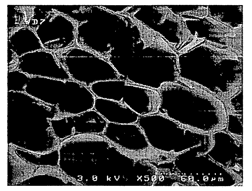
Image

Examples
example 1
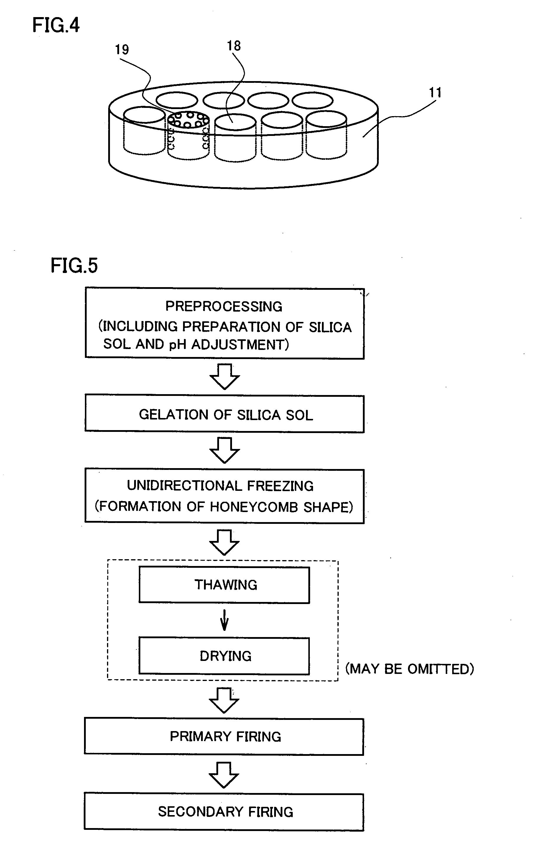
[0148]Sodium silicate solution (manufactured by Wako Pure Chemical Industries, Ltd.) was diluted with deionized distilled water, and 25 mL of sodium silicate aqueous solution having SiO2 concentration of 1.9 mol / L was obtained. To the sodium silicate aqueous solution, 29 mL of H+ type highly acidic ion exchange resin (Amberlite IR120B H AG of Organo Corporation) was added and stirred so that pH of the sodium silicate aqueous solution was adjusted around 2.8, and silica sol was obtained. Here, a tube formed of polypropylene having an inner diameter of 1.3 cm was prepared, and glass beads was filled to about 1 cm at the bottom of the tube. The ion exchange resin was removed from the silica sol, and the silica sol was poured to 5 cm into the tube, the tube was closed with a lid, and left stationary at 30° C. It took 2 hours until the silica sol became uniform silica wet gel.
[0149]Two hours after the formation of silica wet gel, the tube filled with the silica wet gel was inserted to an...
example 2
[0150]Operations similar to those of Example 1 were conducted until the silica sol turned to uniform silica wet gel.
[0151]Two hours after the formation of silica wet gel, the tube filled with the silica wet gel was inserted to an ethanol coolant bath of −30° C., using a constant speed motor set to insert the tube at the insertion rate of 2 cm / h. After the silica wet gel was fully frozen, the tube filled with the silica wet gel was put in a constant temperature bath of 50° C. and the silica wet gel was thawed. After thawing, the silica wet gel was taken out from the tube, and immersed in t-butanol. Thereafter, cleaning with t-butanol was performed at least three times over three days, and the water contained in the silica wet gel was fully replaced by t-butanol. The silica wet gel with the water fully replaced by t-butanol was dried by microwave for 10 minutes, and a honeycomb structure was obtained. The honeycomb structure was cut to the length of 5 mm, immersed in a 0.3 wt % silver...
example 3
[0152]Operations similar to those of Example 1 were conducted until the silica sol turned to uniform silica wet gel.
[0153]Two hours after the formation of silica wet gel, the tube filled with the silica wet gel was inserted to an ethanol coolant bath of −30° C., using a constant speed motor set to insert the tube at the insertion rate of 2 cm / h. After the silica wet gel was fully frozen, the tube filled with the silica wet gel was put in a constant temperature bath of 50° C. and the silica wet gel was thawed. After thawing, the silica wet gel was dried by microwave for 10 minutes, and a honeycomb structure was obtained. The honeycomb structure was cut to the length of 5 mm, immersed in a 0.3 wt % silver colloid paste aqueous solution and dried, whereby a composite honeycomb structure carrying silver was obtained.
PUM
| Property | Measurement | Unit |
|---|---|---|
| pore diameter | aaaaa | aaaaa |
| specific surface area | aaaaa | aaaaa |
| pore diameter | aaaaa | aaaaa |
Abstract
Description
Claims
Application Information