Process for manufacturing electronically conductive components

a manufacturing process and electronic conductive technology, applied in the direction of external electrodes, electromagnets, cores/yokes, etc., can solve the problems of high cost, difficult or impossible time-consuming, labour-intensive manufacturing of wiring and connector components, etc., to minimise the pitting in the sheet and minimise the effect of pitting

Inactive Publication Date: 2007-11-01
COCHLEAR LIMITED
View PDF10 Cites 72 Cited by
  • Summary
  • Abstract
  • Description
  • Claims
  • Application Information

AI Technical Summary

Benefits of technology

[0022] The present application is directed to a method of forming electrical components for an electrical device. The method provides an advantage over the prior art in that it enables multiple electrical components to be formed in a simple and efficient manner, using materials and dimensions not possible with traditional mass production forming methods. The invention uses a sheet of material whose properties do not allow stamping out line widths as narrow as are required in the final assembly and allows multiple miniature components to be formed in very close proximity of dimensions not achievable through traditional stamping processes.
[0170] In a preferred embodiment, the cutting tool has a size and shape that matches the size and shape of the portion of the sheet to be removed from the sheet during the machining steps comprising step (ii). In this embodiment, it is preferred that the tool is brought adjacent the sheet at a number of different locations so as to remove differing portions of the sheet. This multiple use of the tool preferably serves to gradually build up the pattern of the electrode array.

Problems solved by technology

In many electrical devices, particularly those that are manufactured on a very small scale, the manufacture of the wiring and connector components is often a labour intensive and specialised craft.
Ensuring that the wiring and connection of the various components of the systems occurs correctly is often the most expensive and labour intensive aspect of the manufacturing process, resulting in large costs associated with the time taken to manufacture the device which is often passed on to the ultimate consumer.
This is also the case when such devices need to be specifically hand made to a specification as often the availability of the device is dependant upon the time taken to manufacture the device, with the time taken being difficult or impossible to expedite.
As such, manufacturing such devices to ensure that they are reliable and sturdy is a specialised art, and requires much time and expense.
As a result of the need to increase the miniaturisation of such devices, a wide range of techniques have been developed to create patterned components which would be too difficult or impossible to create by hand design and satisfy the high volume supply required.
The problem with such methods however, has been that the metallic films produced by these techniques have been shown to feature properties that are different from the corresponding properties of the bulk materials used.
This results in the desired materials functioning differently from their intended purpose, and in the particular case of platinum, the thin films have tended to crack and exhibit large impedance as well as a high degree of delamination.
Variations in these properties can have a bearing on the functionality of the device, which, particularly in medical implanted devices, is highly undesirable.
As mentioned, platinum films tend to crack and delaminate, hence delivering high impedance which impairs the functionality of the device.
The use of thin film technology has been shown to work for a number of materials such as copper, gold and nickel, however none of these materials are suitable for active implantable devices.
However, simple stamping techniques are not suitable for multiple components having very small dimensions made out of thin conductive sheets, such as those proposed to be covered by the present invention.
In such applications, the line width dimensions of the components and between the components are too small for stamping machines and the sheet material is too thin to provide the precision required for such components.
Because of these problems, medical implants, such as cochlear implants, are still manufactured using labour intensive manual procedures.
In some cases, a person may have hearing loss of both types.
Of these types, conductive hearing loss occurs where the normal mechanical pathways for sound to reach the hair cells in the cochlea are impeded, for example, by damage to the ossicles.
In many people who are profoundly deaf, however, the reason for their deafness is sensorineural hearing loss.
These people are thus unable to derive suitable benefit from conventional hearing aid systems, no matter how loud the acoustic stimulus is made, because there is damage to or absence of the mechanism for nerve impulses to be generated from sound in the normal manner.
As the size of the cochlea is very small and the electrode assembly needs to be flexible enough to be inserted into the cochlea, the dimensions of the electrode assembly are such that do not allow for traditional manufacturing techniques.
While the above method has proven very successful, it is labour intensive and hence a relatively expensive process.

Method used


Image

  • Process for manufacturing electronically conductive components
  • Process for manufacturing electronically conductive components
  • Process for manufacturing electronically conductive components

Examples


Embodiment Construction

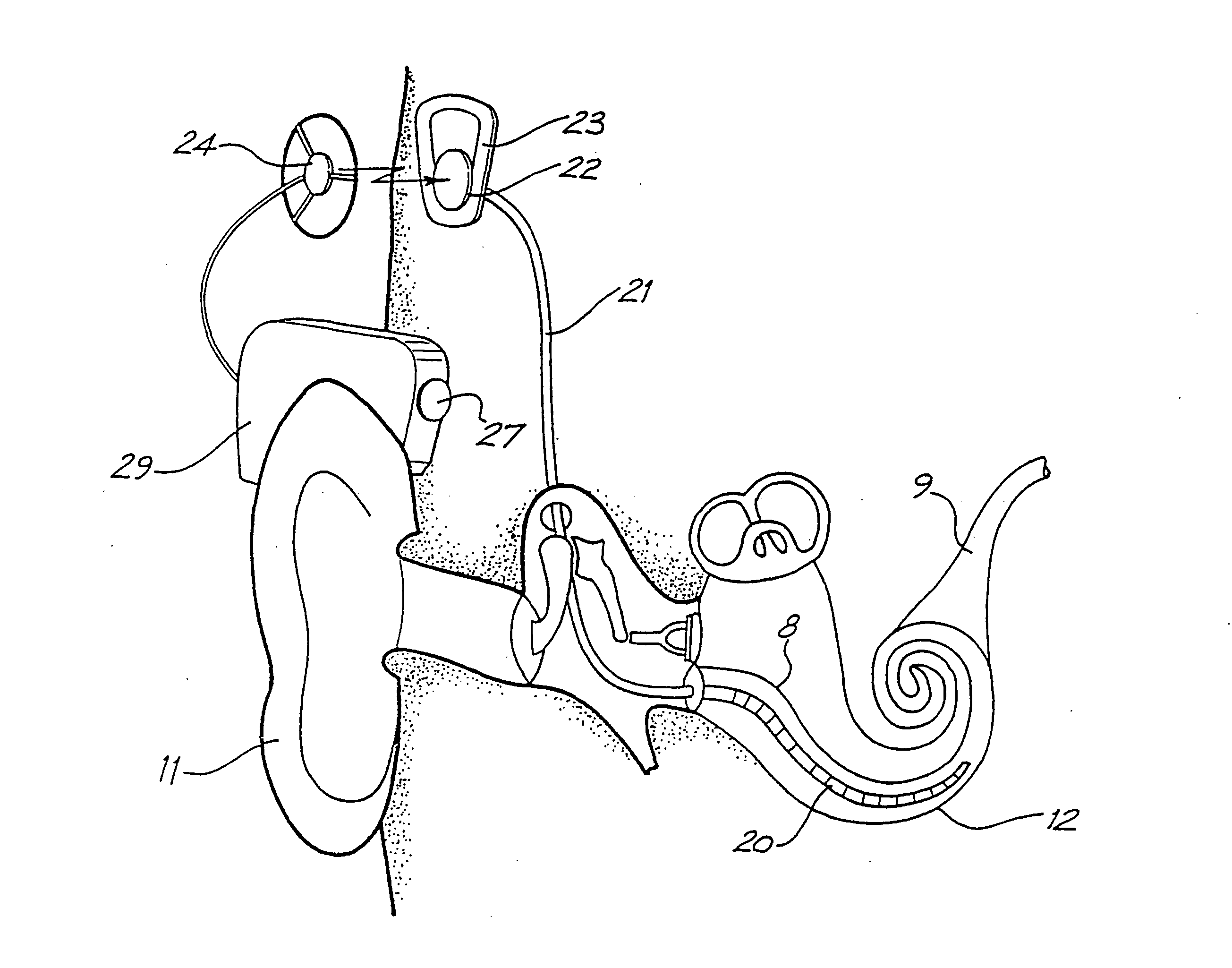
[0202] Before describing the features of the present invention, it is appropriate to briefly describe the construction of one type of known cochlear implant system with reference to FIG. 16.

[0203] Known cochlear implants typically consist of two main components, an external component including a speech processor 29, and an internal component including an implanted receiver and stimulator unit 22. The external component includes a microphone 27. The speech processor 29 is, in this illustration, constructed and arranged so that it can fit behind the outer ear 11. Alternative versions may be worn on the body. Attached to the speech processor 29 is a transmitter coil 24 that transmits electrical signals to the implanted unit 22 via a radio frequency (RF) link.

[0204] The implanted component includes a receiver coil 23 for receiving power and data from the transmitter coil 24. A cable 21 extends from the implanted receiver and stimulator unit 22 to the cochlea 12 and terminates in an el...


PUM

PropertyMeasurementUnit
thicknessaaaaaaaaaa
thicknessaaaaaaaaaa
widthaaaaaaaaaa

Abstract

A method of forming a device, such as an electrode array for a cochlear implant. The method comprises a step of forming a predetermined pattern of relatively electrically conductive regions and relatively electrically resistive regions in a sheet of biocompatible electrically conductive material, such as platinum foil. The method can comprise a step of working on the sheet to remove predetermined portions therefrom to form the one or more discrete relatively conducting regions. The step of working on the sheet can comprise embossing the sheet, cutting or slicing the sheet, or using electrical discharge machining (EDM) to remove unwanted portions of the sheet, the EDM equipment having a cutting tool comprising an electrode.

Description

CROSS-REFERENCE TO RELATED APPLICATION(S) [0001] This application is a divisional of U.S. patent application Ser. No. 10 / 477,434 filed on Nov. 7, 2003 which is a National Phase Patent Application of International Application Number PCT / AU02 / 00575, filed on May 7, 2002, which claims priority of Australian Patent Application Number PR 4818, filed on May 7, 2001, and Australian Patent Application Number PS 1924, filed on Apr. 23, 2002.FIELD OF THE INVENTION [0002] The present invention relates to a method of forming miniature wiring and connector systems for electrical products. More specifically the present invention relates to a method of forming electrode arrays, such as arrays for sensors, including biosensors, and implantable devices, such as an implantable recording or stimulating electrode or pad for use in the body. An electrode array formed using the method is also described. BACKGROUND OF THE INVENTION [0003] In many electrical devices, particularly those that are manufacture...

Claims


Application Information

Patent Timeline
Patent Type & Authority Applications(United States)
IPC IPC(8): H04R31/00A61F11/00A61N1/05
CPCA61N1/0541Y10T29/49002Y10T29/49155Y10T29/4908Y10T29/49476Y10T29/49176Y10T29/49151Y10T29/49004Y10T29/49529Y10T29/49005Y10T29/49128
Inventor MILOJEVIC, DUSANPARKER, JOHN
Owner COCHLEAR LIMITED
Why Eureka
Try Eureka