Pipe

Inactive Publication Date: 2007-11-08
PETRO TECH LTD
View PDF11 Cites 18 Cited by
  • Summary
  • Abstract
  • Description
  • Claims
  • Application Information

AI Technical Summary

Benefits of technology

[0047] Preferably the first fluoropolymer of the inner barrier layer incorporates a dispersed electrically conductive material producing a maximum surface resistivity of 106 Ω/sq. This avoids bu

Problems solved by technology

Since the primary source of leaks is at the joints and fittings of a system, such systems are prone to leakage.
In addition, the many fittings are adversely affected by ground movement during the life of the fluid system as well as by improper installation and environmental degradation such as corrosion.
However, there remains great public concern because chemicals are still penetrating into underground water supplies and vapours diffusing into sub-surface soil, contaminating public drinking water and making some of the food supply unusable, amongst other things.
According to some, the entire environment is being downgraded to a serious level which tends to cast doubt on the future availability of safe water.
This problem is exacerbated by the fact that all pipe manufactured from pla

Method used


Image

  • Pipe
  • Pipe
  • Pipe

Examples


Example

EXAMPLE 1

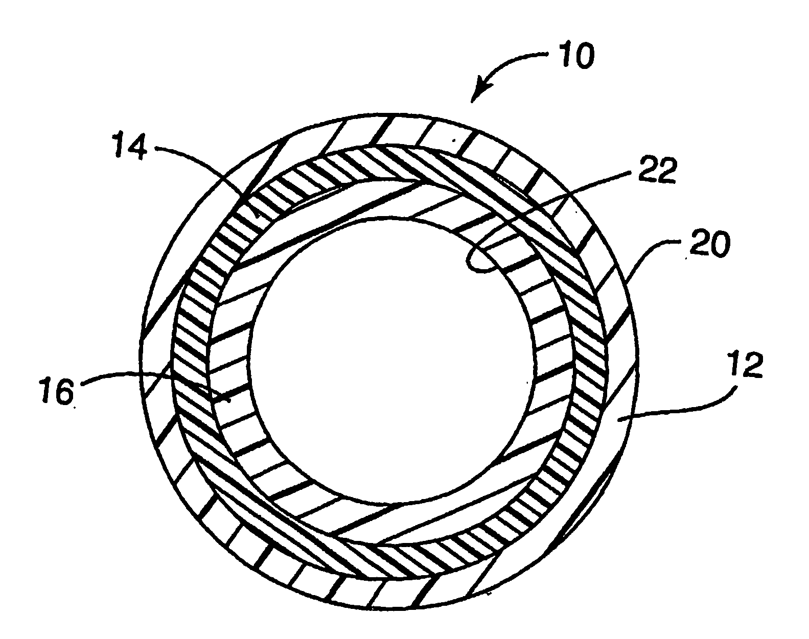
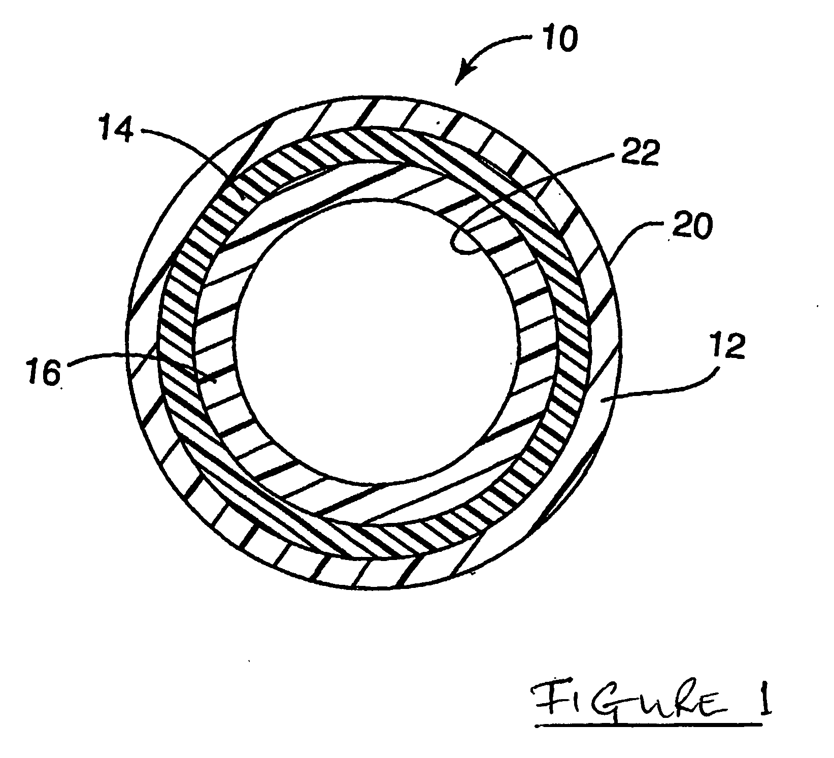
[0127] If the primary pipe were 32 mm in diameter, the construction would be typically: [0128] Inner, fluoropolymer: e.g. modified PVDF=0.3 mm [0129] Bulk layer: e.g. PA12=0.3 mm [0130] Outer layer: e.g. modified PVDF=2.5 mm

[0131] The secondary would be an exact copy of this, fitting snugly on top, or could be a monolayer of fluoropolymer.

Example

EXAMPLE 2

[0132] In this example, assuming a pipe diameter of 32 mm, the outer fluorinated layer is formed by fluorination of polyethylene. The construction would typically be:—[0133] an inner fluoropolymer barrier layer of modified PVDF=0.3 mm; [0134] an intermediate core layer of polyethylene=2.7 mm, the outer surface of which is fluorinated as described above.

Example

EXAMPLE 3

[0135] Corresponds to Example 2 with a tie layer between the PVDF layer and the PE layer. The construction of this type would typically be:—[0136] an inner, fluoropolymer barrier layer of PVDF—0.3 mm [0137] a tie layer e.g. Adheflon from AtoFina—0.1 mm [0138] an intermediate, core layer of polyethylene=2.7 mm, the outer surface of which is fluorinated as described above.


PUM

PropertyMeasurementUnit
Flexibilityaaaaaaaaaa
Permeabilityaaaaaaaaaa

Abstract

A flexible multi-layer pipe assembly comprising, in a radial direction from the inside to the outside:—(i) an inner barrier layer formed from a first fluoropolymer; (ii) an intermediate or core layer formed from a polymer or blend of polymers; (iii) an outer barrier layer formed from a second fluoropolymer.

Description

FIELD OF THE INVENTION [0001] The present invention relates to pipes suitable for the transmission of fluids. It is particularly applicable to pipes having a multi-layer structure and having very low permeability to fuels such as petroleum and to the various additives used in such fuels. [0002] While the invention is particularly applicable to double walled pipe assemblies used in the petroleum, chemical and natural gas industries, it should be appreciated that such a pipe assembly can be utilized in connection with any type of installation in which leakage of a hazardous fluid, be it a liquid, a gas or a vapour, into the surrounding environment over long periods of time and without detection will produce extensive pollution and an environmental hazard. Such pollution is likely to be difficult and expensive to clean up when it is ultimately found. BACKGROUND TO THE INVENTION [0003] A conventional underground fluid piping systems such as is utilized in, e.g. a service station environ...

Claims


Application Information

Patent Timeline
IPC IPC(8): B29D22/00B32B1/08F16L9/12
CPCB32B1/08F16L9/121Y10T428/1386Y10T428/1352F16L2011/047F16L11/04
Inventor BOUDRY, JOHN ALEXANDRECOOK, MARK
Owner PETRO TECH LTD
Why Eureka
Try Eureka