Method of forming fine pattern using azobenzene-functionalized polymer and method of manufacturing nitride-based semiconductor light emitting device using the method of forming fine pattern

a technology of azobenzene and functionalized polymers, which is applied in the field of pattern formation, can solve the problems of increased manufacturing costs of electron beam lithography, difficulty in forming pattern dimensions of 1 m or less, and inconvenient use of masks and lenses in conventional light lithographic methods, etc., and achieves the effect of improving light extraction efficiency and optical power

Inactive Publication Date: 2007-11-15
SAMSUNG ELECTRONICS CO LTD
View PDF9 Cites 9 Cited by
  • Summary
  • Abstract
  • Description
  • Claims
  • Application Information

AI Technical Summary

Benefits of technology

[0012]In another embodiment, a method of forming a fine pattern having a pattern dimension of 1 μm or less can be reproduced repeatedly using the method. In addition, when the nitride-based semiconductor light-emitting device is manufactured using the method of forming a fine pattern, a photonic crystal structure having improved optical power and light extraction efficiency is obtained.

Problems solved by technology

Since the method uses light, it is difficult to form a pattern having a pattern dimension of 1 μm or less.
However, a mask and a lens as used in conventional light lithographic methods are not useful in EUV lithography due to the smaller feature sizes which require improved mask technology, and the high absorbance of conventional lens materials at EUV wavelengths.
However, since Electron beam lithography has increased manufacturing costs and is difficult to achieve accurate results, Electron beam lithography is not commonly used in a method of manufacturing an element.
However, for these methods of forming patterns, materials used are limited and reproducibility is poor.
In particular, it is difficult to form a pattern having a pattern dimension of 1 μm or less.

Method used


Image

  • Method of forming fine pattern using azobenzene-functionalized polymer and method of manufacturing nitride-based semiconductor light emitting device using the method of forming fine pattern
  • Method of forming fine pattern using azobenzene-functionalized polymer and method of manufacturing nitride-based semiconductor light emitting device using the method of forming fine pattern
  • Method of forming fine pattern using azobenzene-functionalized polymer and method of manufacturing nitride-based semiconductor light emitting device using the method of forming fine pattern

Examples


Embodiment Construction

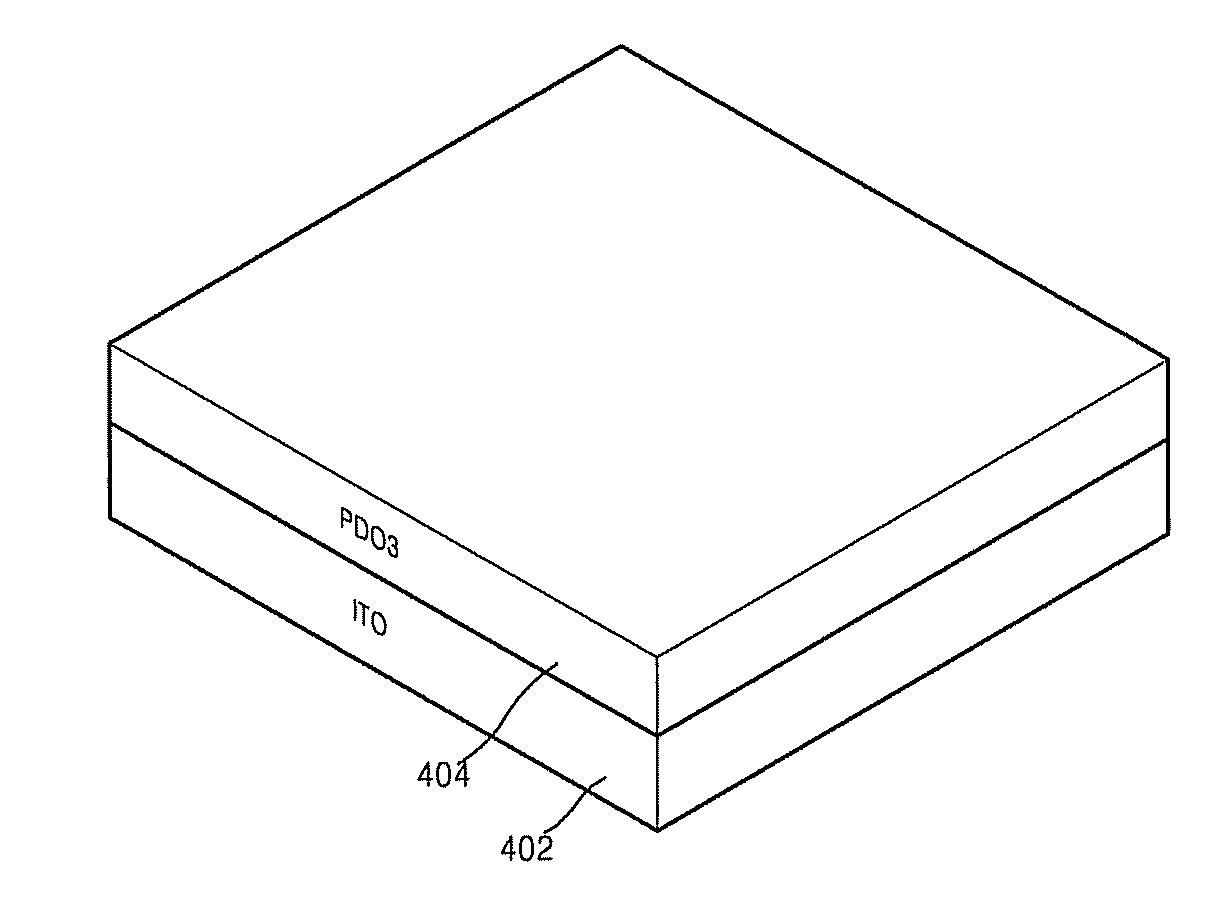
[0021]The present invention will now be described more fully with reference to the accompanying drawings, in which exemplary embodiments of the invention are shown. The invention may, however, be embodied in many different forms and should not be construed as being limited to the embodiments set forth herein; rather, these embodiments are provided so that this disclosure will be thorough and complete, and will fully convey the concept of the invention to those skilled in the art. In the drawings, the thickness of layers and region are exaggerated for clarity.

[0022]It will be understood that when an element is referred to as being “on” another element, it can be directly on the other element or intervening elements may be present therebetween. In contrast, when an element is referred to as being “disposed on” another element, the elements are understood to be in at least partial contact with each other, unless otherwise specified.

[0023]The terminology used herein is for the purpose o...


PUM

PropertyMeasurementUnit
temperatureaaaaaaaaaa
wavelengthsaaaaaaaaaa

Abstract

Provided is a method of forming a fine pattern having a pattern dimension of 1 μm or less, repeatedly with reproducibility. The method of forming the fine pattern includes: forming an azobenzene-functionalized polymer film on an etched layer; irradiating the azobenzene-functionalized polymer film using an interference laser beam to form a patterned azobenzene-functionalized polymer film having fine-patterned surface relief gratings by a photophysical mass transporting of the azobenzene-functionalized polymer; etching the etched layer using the azobenzene-functionalized polymer film having the surface relief grating patterns as an etching mask; and removing the patterned azobenzene-functionalized polymer film.

Description

[0001]This application claims priority to Korean Patent Application No. 10-2006-0042385, filed on May 11, 2006, and all the benefits accruing therefrom under 35 USC § 119(a), the content of which is incorporated herein by reference in its entirety.BACKGROUND OF THE INVENTION[0002]1. Field of the Invention[0003]The present invention relates to a method of forming a pattern, and more particularly, to a method of forming a fine pattern, in which a nanopattern having a pattern dimension of 1 μm or less can be repeatedly reproduced, simply and easily, and to a method of manufacturing a nitride-based semiconductor light emitting device using the method of forming a fine pattern.[0004]2. Description of the Related Art[0005]A method of forming a pattern using a conventional light lithographic method such as, for example, g-Line lithography using light having a wavelength of 436 nm, i-line lithography using ultraviolet (“UV”) light at a wavelength of 365 nm, or deep-UV lithography using ligh...

Claims


Application Information

Patent Timeline
Patent Type & Authority Applications(United States)
IPC IPC(8): G03C5/00H01L29/808H01L33/22H01L33/32H01L33/38H01L33/42
CPCG03F7/004H01L33/42H01L33/22G03F7/36
Inventor CHO, JAE-HEESONE, CHEOL-SOOKIM, DONG-YUHONG, HYUN-GIKIM, SEOK-SOON
Owner SAMSUNG ELECTRONICS CO LTD
Why Eureka
Try Eureka