Apparatus and Method for Growing Biological Organisms for Fuel and Other Purposes

a technology of photosynthesis and photosynthesis, applied in the field of apparatus and a method for growing biological organisms, can solve the problems of reducing the productivity of the organism, reducing the efficiency of the organism, and limiting the current design of the bioreactor to operation during sunlight, so as to reduce the space consumption of the structure, increase the algal productivity, and increase the effect of productivity

Active Publication Date: 2007-11-15
OHIO UNIV
View PDF7 Cites 60 Cited by
  • Summary
  • Abstract
  • Description
  • Claims
  • Application Information

AI Technical Summary

Benefits of technology

[0012]The bioreactor of the invention addresses significant problems of conventional bioreactor designs. First, the invention uses solar collecting and transmitting features so that photosynthetically active radiation can be delivered to the microalgae at optimal levels. Second, the invention uses a fiber hanger so that light transmission fibers are terminated inside the bioreactor, thereby providing the direct application of light without a separate distribution system. Third, the invention uses an algal slurry to increase productivity over a biofilm system. The circulating slurry uses transport processes to create dark zones that are internal to the bioreactor to provide time for dark reactions, and thus potentially greatly increasing algal productivity. Finally, the light transmission and distribution system permits the bioreactor to be built in the vertical direction, thereby decreasing the structure's space consumption over a pond or raceway cultivator.

Problems solved by technology

Current bioreactor designs are limited to operation during sunlight hours, primarily because their design is entirely predicated on getting light from the outside and having it penetrate by transmission through transparent walls to the algae.
A simple economic analysis shows that use of only artificial light is too expensive.
However, by not having production during the nighttime hours when no available solar energy, significant productivity is lost.

Method used


Image

  • Apparatus and Method for Growing Biological Organisms for Fuel and Other Purposes
  • Apparatus and Method for Growing Biological Organisms for Fuel and Other Purposes
  • Apparatus and Method for Growing Biological Organisms for Fuel and Other Purposes

Examples


Embodiment Construction

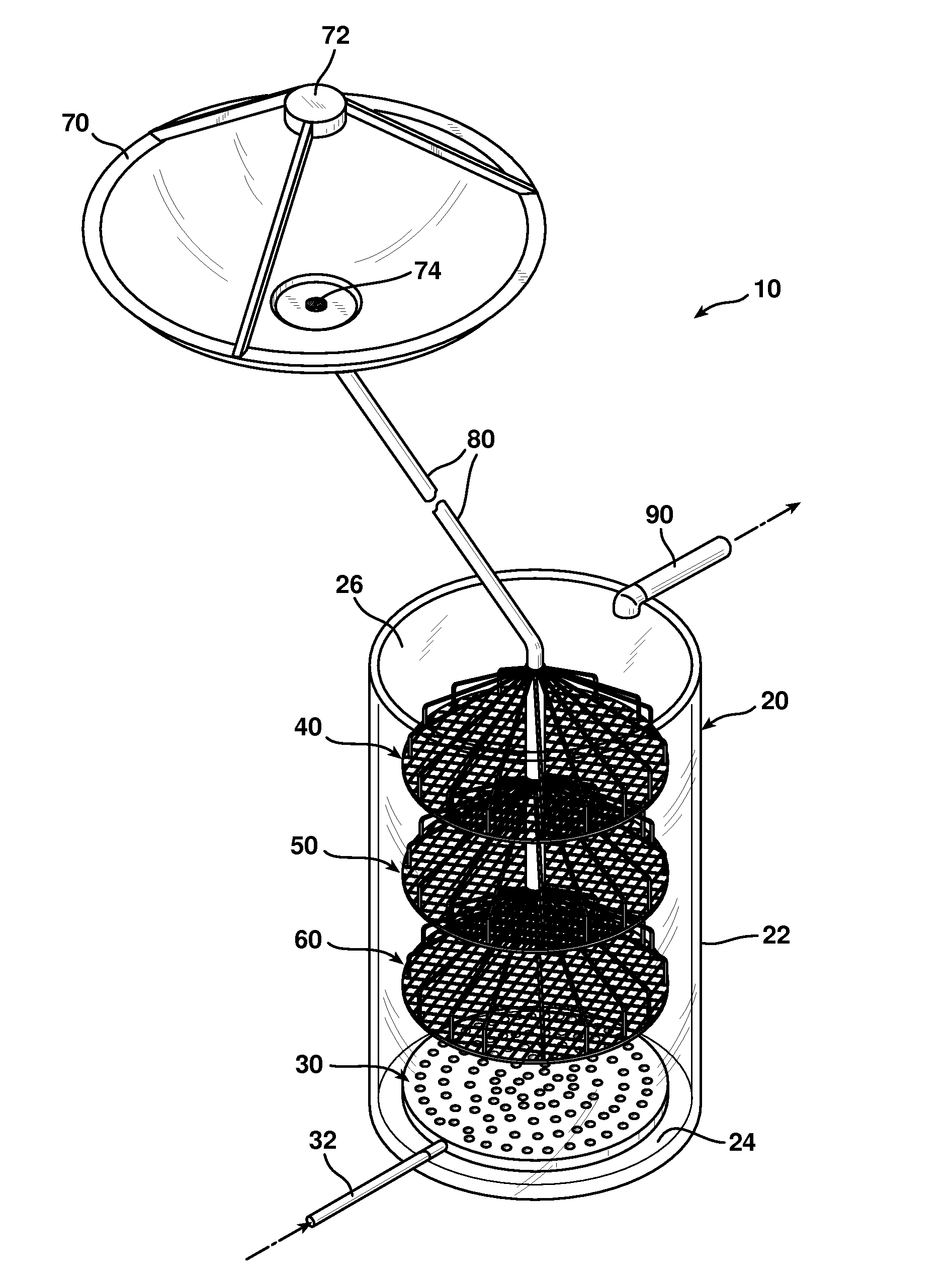
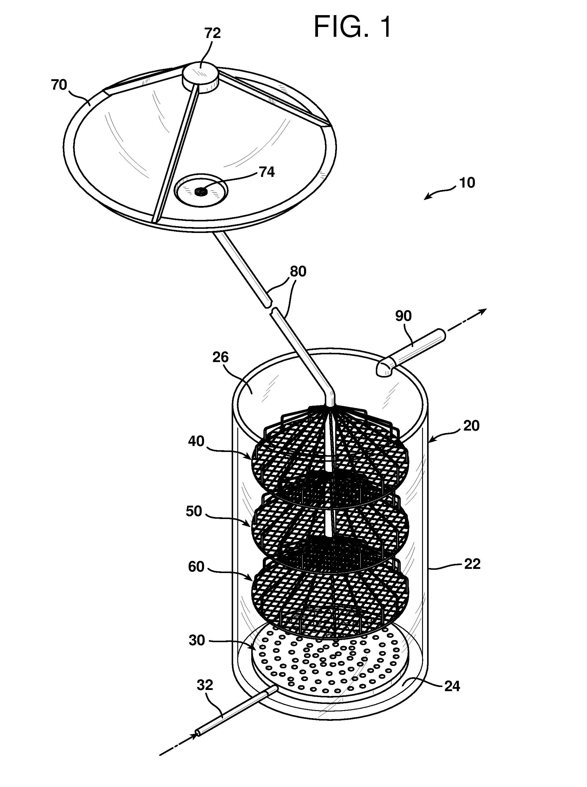
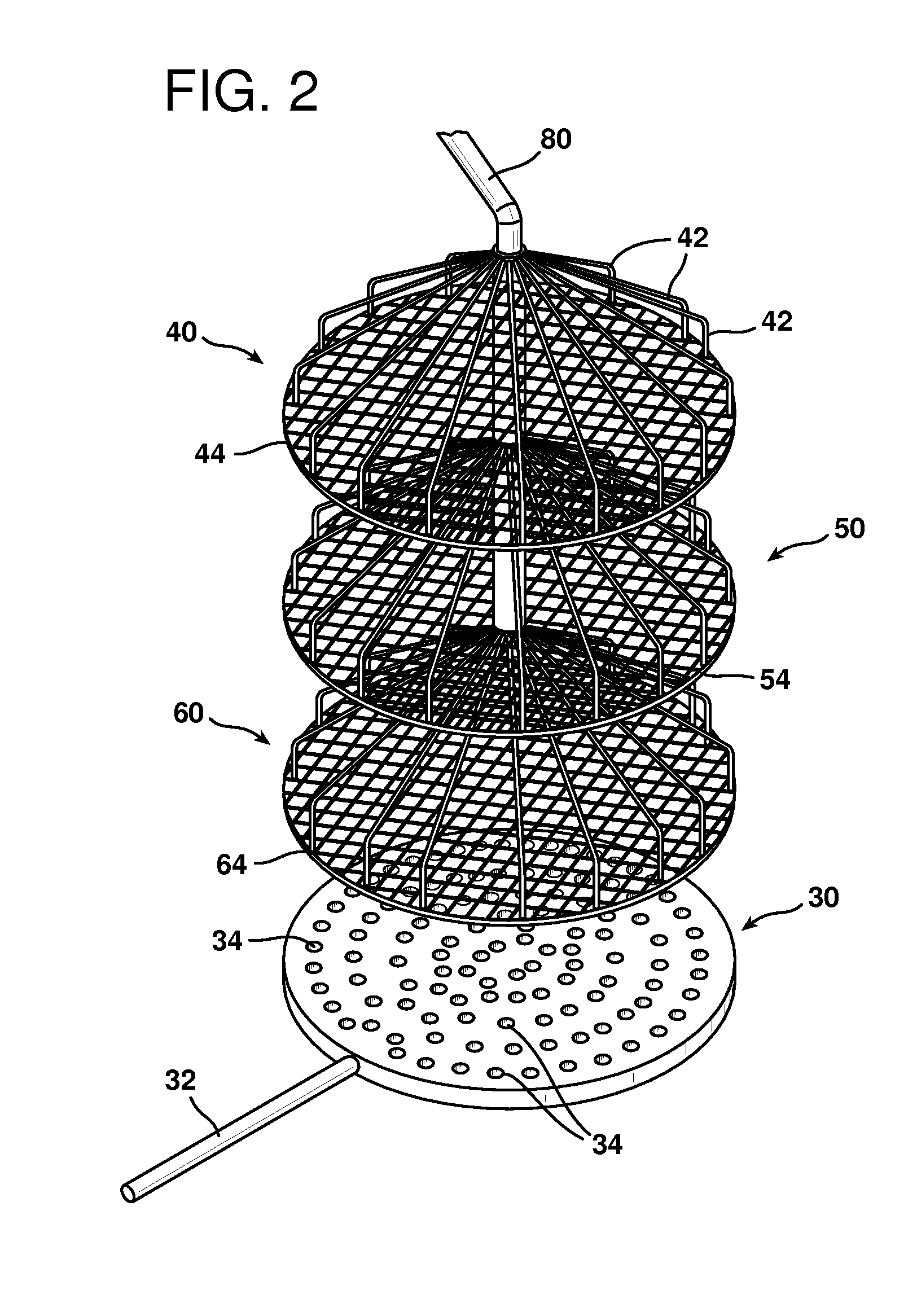
[0020]The preferred embodiment of the present invention is shown in FIG. 1, in which the bioreactor 10 is shown in a preferred configuration. The container 20 is a cylindrical tube having a sidewall 22 a floor 24 and a ceiling 26. The container 20 is preferably approximately four inches in diameter, and approximately seven feet tall. The container 20 is can be made of a plastic material, such as transparent acrylic or polycarbonate, or it can be made of an opaque metal or other material. The container 20 does not have to be transparent, but it can be. It will become apparent that the material of which the container 20 is made must be strong enough to contain a water and algae mixture, but need not have light-transmission characteristics, even though such characteristics are contemplated. Of course, composites, ceramics and other plastics are contemplated for the material of which the container 20 is made. The container 20 defines a chamber that is preferably substantially full of wa...


PUM

PropertyMeasurementUnit
diameteraaaaaaaaaa
diameteraaaaaaaaaa
diameteraaaaaaaaaa

Abstract

A bioreactor apparatus in which a container has sidewalls, a floor and a ceiling defining a chamber that contains a slurry of water, nutrients and photosynthetic microorganisms. A plurality of optical fibers, each of which has a first end disposed outside the chamber and a second end in the mixture. A light collector spaced from the container has light incident on it and focuses the light onto the first ends of the plurality of optical fibers, thereby permitting the light to be conveyed into the mixture to promote photosynthesis. At least one nozzle is in fluid communication with a source of gas, such as exhaust gas from a fossil-fuel burning power plant containing carbon dioxide. The nozzle is disposed in the mixture beneath the second ends of the optical fibers for injecting the gas into the mixture.

Description

BACKGROUND OF THE INVENTION[0001]1. Field of the Invention[0002]This invention relates to an apparatus and a method for growing photosynthetic microorganisms, possibly from exhaust gas containing carbon dioxide.[0003]2. Description of the Related Art[0004]It is well known that fossil fuels, such as petroleum-derived fuels and coal, are limited in supply. Additionally, the combustion of such fuels contributes substantial carbon to the atmosphere. The release of carbon long stored in such fuels is the subject of global concern relating to climate change and other environmental problems. Nevertheless, fossil fuels are the largest fuel source for automobiles and energy production facilities.[0005]Biofuels are derived from recently living organisms or their metabolic byproducts, but contain different hydrogen and carbon containing molecules than fossil fuels. Biofuels contain sufficient enthalpy to compete with fossil fuels for vehicle fuel and energy production. Most biofuels are consid...

Claims


Application Information

Patent Timeline
Patent Type & Authority Applications(United States)
IPC IPC(8): C12M1/00C12N1/12
CPCB01D53/84B01D2251/95B01D2257/504Y02C10/02C12M29/06C12M31/08C12M43/06C12M21/02Y02P20/59Y02A50/20Y02C20/40C12M1/002C12M1/04C12M3/00
Inventor BAYLESS, DAVID J.VIS-CHIASSON, MORGAN LEFAYSTUART, BENKREMER, GREGORY G.
Owner OHIO UNIV
Why Eureka
Try Eureka