
Substrate Heating Apparatus and Substrate Heating Method

a heating apparatus and substrate technology, applied in the direction of electrostatic spraying apparatus, coating, basic electric elements, etc., can solve the problems of increasing the unit price of a product, insufficient amount of proton (ht) generated inside a chemically amplified resist, and small amount of energy injected from a low acceleration electron beam to a resis

Inactive Publication Date: 2007-11-29
TOKYO ELECTRON LTD +1
View PDF16 Cites 31 Cited by
  • Summary
  • Abstract
  • Description
  • Claims
  • Application Information

AI Technical Summary

Benefits of technology

The invention is a substrate processing apparatus and method that uses a resist pattern for precise line width in a chemical amplification reaction. The apparatus includes a mounting table for heating the substrate, a fluid supply mechanism for accelerating acid catalysis in the resist, and a heater for heating the substrate. The apparatus also has a fluid control member that holds the resist reforming fluid in a clearance above the substrate, and a cooling liquid supply port for cooling the substrate after heating. The method involves supplying the resist reforming fluid to the substrate before placing it on the mounting table, and using a fluid control member to adjust the clearance between the substrate and the fluid control member. The invention improves the efficiency and throughput of the process.

Problems solved by technology

Therefore, production of an exclusive mask for each type of product increases a unit price of a product.
However, in electron beam writing exposure, the amount of energy injected from a low acceleration electron beam to a resist is small, and the amount of proton (Ht) generated inside a chemically amplified resist is insufficient.
Acid catalysis is not accelerated, and a resist is not sufficiently reformed.
A problem of trading off a low beam acceleration and high throughput will be more apparent.
Because, a high-acceleration electron beam passes through a resist without exposing a resist (the effective sensitivity of the resist is low), a proton (H+) is insufficiently produced, and acid catalysis is not accelerated.
However, by setting the electron beam application time long, a processing throughput is decreased.
For this reason, electron beam writing exposure is practically difficult.

Method used


Image

  • Substrate Heating Apparatus and Substrate Heating Method
  • Substrate Heating Apparatus and Substrate Heating Method
  • Substrate Heating Apparatus and Substrate Heating Method

Examples


embodiment 1

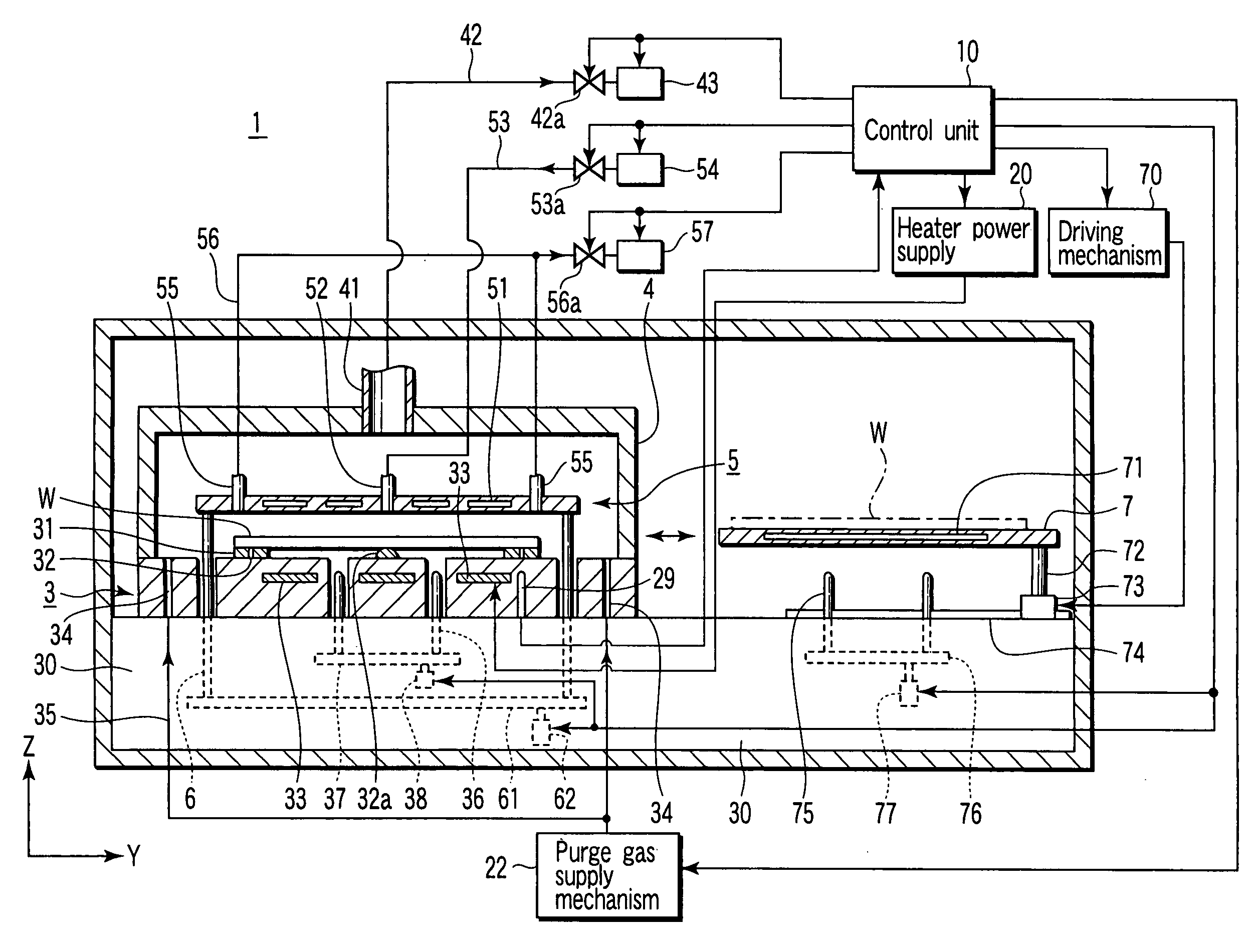
[0053] Explanation will be given on a substrate heating apparatus and method according to a first embodiment of the invention with reference to FIG. 4-FIG. 8. In this embodiment, an explanation will be given on an example of a heating-cooling unit formed by combining a cooling unit with a heating unit as a substrate heating apparatus of the invention. But, a cooling unit may be provided independently of a heating unit.

[0054] A heating unit and a cooling unit are provided in the housing of the heating-cooling apparatus 1, as shown in FIG. 4 and FIG. 5. The heating unit is placed on the left side in the drawing, and is provided with a mounting table 3 having a heater 33 buried inside, a cover unit 4, and a fluid control plate 5. The cooling unit is placed on the right side in the drawing, and is provided with a cooling plate 7 containing a coolant 71.

[0055] The mounting table 3 is provided on a foundation 30, on which a wafer W is placed horizontally. The inside of the foundation 30...

embodiment 2

[0100] A second embodiment will be explained with reference to FIG. 9 and FIG. 10. Explanation on the same components as those explained in the first embodiment will be omitted.

[0101] A unit 1A according to a second embodiment is provided with a fluid supply unit 54A to supply a glycerin-contained mist or vapor to a clearance between the wafer W and fluid control plate 5. The fluid supply unit 54A contains a first tank to contain glycerin, a second tank to contain a solvent, a mass flow controller (MFC), a mixer, and a vaporizer. The vaporizer has a spray nozzle to mechanically or physically spray a mixture of glycerin and solvent as a fine liquid drop. As a solvent, one of alcohol and organic solvent can be used.

[0102] An internal flow path of the fluid supply unit 54A is connected to the supply port 52A of the fluid control plate 5 through the flexible piping 53. The flexible pipe is provided with a valve 53a. The control unit 10A controls the fluid supply unit 54A, valve 53a, h...

embodiment 3

[0110] A substrate heating apparatus according to a third embodiment will be explained with reference to FIG. 11. Explanation on the same components as those explained in the embodiments described hereinbefore will be omitted.

[0111] A substrate heating apparatus 1B of this embodiment is substantially the same as the apparatus 1 of the first embodiment except having a means for supplying the wafer W with a cooling liquid compatible with a rinse liquid as a cleaning liquid for cleaning the wafer W. In the apparatus 1B, the supply piping 53 connected to the fluid supply port 52 is branched halfway and connected to a supply source 8 of a cooling liquid, for example, pure water adjusted in temperature, so that one of the resist reforming fluid and cooling water is supplied to the upper surface of the wafer W through the fluid supply port 52 by a three-way valve 81 operated by a control unit 10B.

[0112] A brief explanation will be given on a process of heating the wafer W by FEB by using...


PUM


Abstract

A substrate heating apparatus for heating a substrate coated with a film of chemically amplified resist within a period after exposure and before development, having a mounting table to mount the substrate substantially horizontal with the resist-coated film faced up, a fluid supply mechanism for supplying glycerin to the substrate, and a heating mechanism for heating the substrate on a mounting table, in a state that glycerin contacts a resist-coated film, wherein the substrate on a mounting table is heated, in a state that glycerin contacts the resist-coated film.

Description

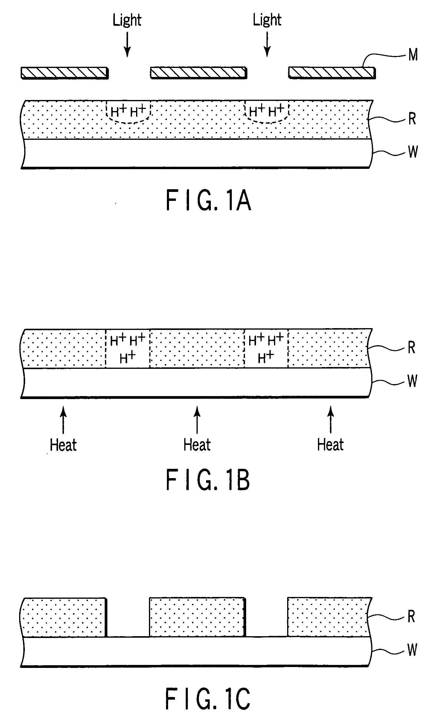
TECHNICAL FIELD [0001] The present invention relates to a substrate heating apparatus and method for coating a substrate with a chemically amplified resist, and baking the resist-coated film after exposure and before development (Post Exposure Bake; PEB). BACKGROUND ART [0002] A photolithography process of semiconductor device uses a system incorporating a coating-developing apparatus in an exposure apparatus. As a line width of a circuit pattern reaches a deep submicron range, a chemically amplified resist is mainly used in a coating-developing apparatus. A chemically amplified resist contains an acid-generating agent to generate acid when heated. When a heating process called PEB (Post Exposure Bake) is performed, the acid diffuses in an exposure area and acid catalysis occurs. [0003]FIG. 1A-FIG. 1C are schematic illustrations showing exposing, heating and developing processes by using a positive chemically amplified resist. First, perform pattern exposure for a wafer W coated wit...

Claims


Application Information

Patent Timeline
Patent Type & Authority Applications(United States)
IPC IPC(8): B05D1/18B05B5/00
CPCG03F7/38H01L21/67748H01L21/67109
Inventor NISHI, TAKANORIKITANO, TAKAHIROOKUMURA, KATSUYA
Owner TOKYO ELECTRON LTD
Learn More