Plasma processing method and apparatus

a processing method and apparatus technology, applied in the field of plasma processing technology, can solve the problems of increasing the non-operation time of the apparatus, reducing the yield of the fabrication of the semiconductor device, and unacceptable semiconductor devices, and achieve the effect of high accuracy

Inactive Publication Date: 2007-12-06
HITACHI HIGH-TECH CORP
View PDF6 Cites 25 Cited by
  • Summary
  • Abstract
  • Description
  • Claims
  • Application Information

AI Technical Summary

Benefits of technology

[0009]With the foregoing problems in view, the present invention has as a principal object the provision of a plasma processing technology which makes it possible to determine the end of seasoning with high accuracy by a versatile method.

Problems solved by technology

The deposited dust particles cause short-circuiting, breakage and / or incomplete etching of interconnecting electrical conductors of integrated circuits arranged on the substrate surfaces, and hence, become a cause of unacceptable semiconductor devices.
Such dust particles, therefore, lead to a reduction in yield in the fabrication of semiconductor devices.
The processing of such many dummy wafers leads to an increase in the non-operation time of the apparatus, and hence, to a rise in the fabrication cost of semiconductor devices.
According to the above-described method of the conventional technology, however, data conditions for use in the determination of the end of seasoning have to be set newly depending upon the processing conditions for substrates, thereby making it difficult to apply the above-described method.
Moreover, it may be difficult to determine the end depending upon the extent of the wet cleaning or the conditions of seasoning.

Method used


Image

  • Plasma processing method and apparatus
  • Plasma processing method and apparatus
  • Plasma processing method and apparatus

Examples


example 4

[0065]In this example, the time required until the internal pressure of the processing chamber reached a constant pressure when the residual gas in the processing chamber was discharged by the turbomolecular pump subsequent to seasoning making use of Si wafers (dummy wafers) was chosen as a parameter to be monitored, and the transition of changes in this time was monitored.

[0066]After applying wet cleaning to two etching apparatus (apparatus 1, apparatus 2) of the same specification, vacuuming was initiated to reduce the internal pressure of each processing chamber to 0.0005 Pa or lower. After the out-gas rate in the processing chamber at that time was confirmed to be 0.08 Pa·L / sec or lower, seasoning was performed using fresh Si wafers (dummy wafers).

[0067]A plasma was then produced, for example, by controlling the processing pressure at 0.4 Pa, setting the plasma-producing power at 600 W and using a mixed gas of Cl2 / HBr / O2 as a processing gas, and under the condition that a RF bia...

example 5

[0072]In this example, the matching electrostatic capacitance of each capacitor as a component in the matching network 105 (source RF bias matching network) was chosen as a parameter to be monitored, and the transition of changes in the capacitance was monitored.

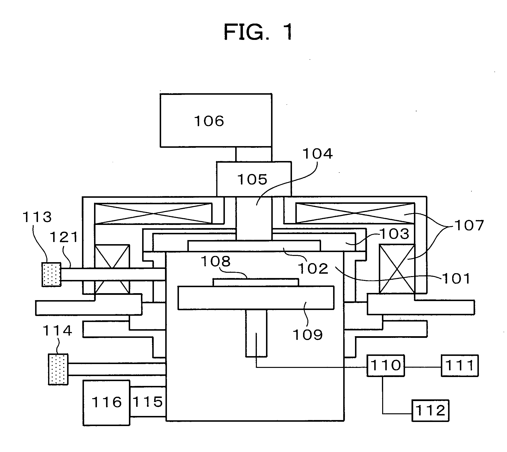
[0073]FIG. 7 illustrates the construction of the matching network 105. In FIG. 7, numeral 71 indicates a coaxial line which connects the plasma-producing RF power source 106 and the waveguide 104 with each other. Designated at numerals 72, 73, 74 are branch lines all connected to the coaxial line 71. A resonance circuit formed of a capacitor C1 and reactor L1 is inserted in the branch line 72, a resonance circuit formed of a capacitor C2 and reactor L2 is inserted in the branch line 73, and a resonance circuit formed of a capacitor C3 and reactor L3 is inserted in the branch line 74.

[0074]FIGS. 8A to 8C illustrate the transition of changes in the capacitances (matching capacitances) of the capacitors C1, C2, C3 as components...

example 6

[0077]In this example, the plasma ignition time, which is the time from the application of plasma-producing RF power to the production of a plasma, was chosen as a parameter to be monitored.

[0078]After applying wet cleaning to each of two etching apparatus (apparatus 1, apparatus 2) of the same specification, vacuuming was initiated. The internal pressure of each processing chamber was set at 0.0005 Pa or lower. Subsequently, Si wafers (dummy wafers) were transferred in turn into each processing chamber to repeat seasoning. During that seasoning, the plasma ignition time was monitored by the photodetector 113.

[0079]As seasoning conditions, the plasma-producing power at 400 W, a mixed gas of Ar / CF4 / CHF3 / O2 was used as a processing gas, and a RF bias to be applied to the lower electrode was set at 150 W.

[0080]FIG. 9 shows the transition of changes in the plasma ignition time versus the seasoning time after wet cleaning. As shown in FIG. 9, the plasma ignition time was unsteady in both...


PUM

PropertyMeasurementUnit
temperatureaaaaaaaaaa
flow ratesaaaaaaaaaa

Abstract

Plasma processing of plural substrates is performed in a plasma processing apparatus, which is provided with a plasma processing chamber having an antenna electrode and a lower electrode for placing and retaining the plural substrates in turn within the plasma processing chamber, a gas feeder for feeding processing gas into the processing chamber, a vacuum pump for discharging gas from the processing chamber via a vacuum valve, and a solenoid coil for forming a magnetic field within the processing chamber. At least one of the plural substrates is placed on the lower electrode, and the processing gas is fed into the processing chamber. RF power is fed to the antenna electrode via a matching network to produce a plasma within the processing chamber in which a magnetic field has been formed by the solenoid coil. This placing of at least one substrate and this feeding of the processing gas are then repeated until the plasma processing of all of the plural substrates is completed. An end of seasoning is determined when a parameter including an internal pressure of the processing chamber has become stable to a steady value with plasma processing time.

Description

FIELD OF THE INVENTION[0001]This invention relates to a plasma processing technology, and especially to a plasma processing technology that makes it possible to determine the end of seasoning with high accuracy.DESCRIPTION OF THE BACKGROUND[0002]A plasma processing apparatus has a processing chamber to contain one or more substrates such as semiconductor substrates, and during plasma processing of the substrate or substrates, nonvolatile reaction products occur and deposit on an inner wall and the like of the processing chamber. In the subsequent processing, the deposit may separate from the inner wall and the like of the processing chamber and may fall and deposit as dust particles on substrate surface or surfaces under processing. It is to be noted that in the background art to be described hereinafter, the processing chamber will be assumed to contain a plurality of substrates at the same time.[0003]The deposited dust particles cause short-circuiting, breakage and / or incomplete e...

Claims


Application Information

Patent Timeline
Patent Type & Authority Applications(United States)
IPC IPC(8): C23F1/00H01L21/302C23C16/00
CPCH01J37/321H01J37/32963H01J2237/3341H01J2237/327H01J2237/24592H01J37/32926H01L21/67069H01J37/32825H01J37/32568H01J37/32082H01J2237/1825H01L21/3065H01J37/32091H01J37/3211H01J37/32192H01J37/32917H01J37/32935H01J37/32981H01J37/3299H01L21/67242H05H1/46
Inventor IKEGAMI, EIJIIKUHARA, SHOJISHIMADA, TAKESHIKUWABARA, KENICHIARASE, TAKAOMATSUMOTO, TSUYOSHI
Owner HITACHI HIGH-TECH CORP
Why Eureka
Try Eureka