
Circulation system for sliding pressure steam generator

a steam generator and circulator system technology, applied in the direction of machines/engines, steam separation arrangements, lighting and heating apparatus, etc., can solve the problems of high cost of spiral furnace design, limited sliding pressure operation of vertical tubes once-through boilers, and increased costs of spiral furnace design

Inactive Publication Date: 2007-12-13
THE BABCOCK & WILCOX CO
View PDF7 Cites 23 Cited by
  • Summary
  • Abstract
  • Description
  • Claims
  • Application Information

AI Technical Summary

Benefits of technology

[0015]It is an object of the present invention to provide a circulation system that allows a steam generator to be operated either as a natural circulation drum steam generator or a sliding pressure once-through steam generator, without orificing and circulation pumps.
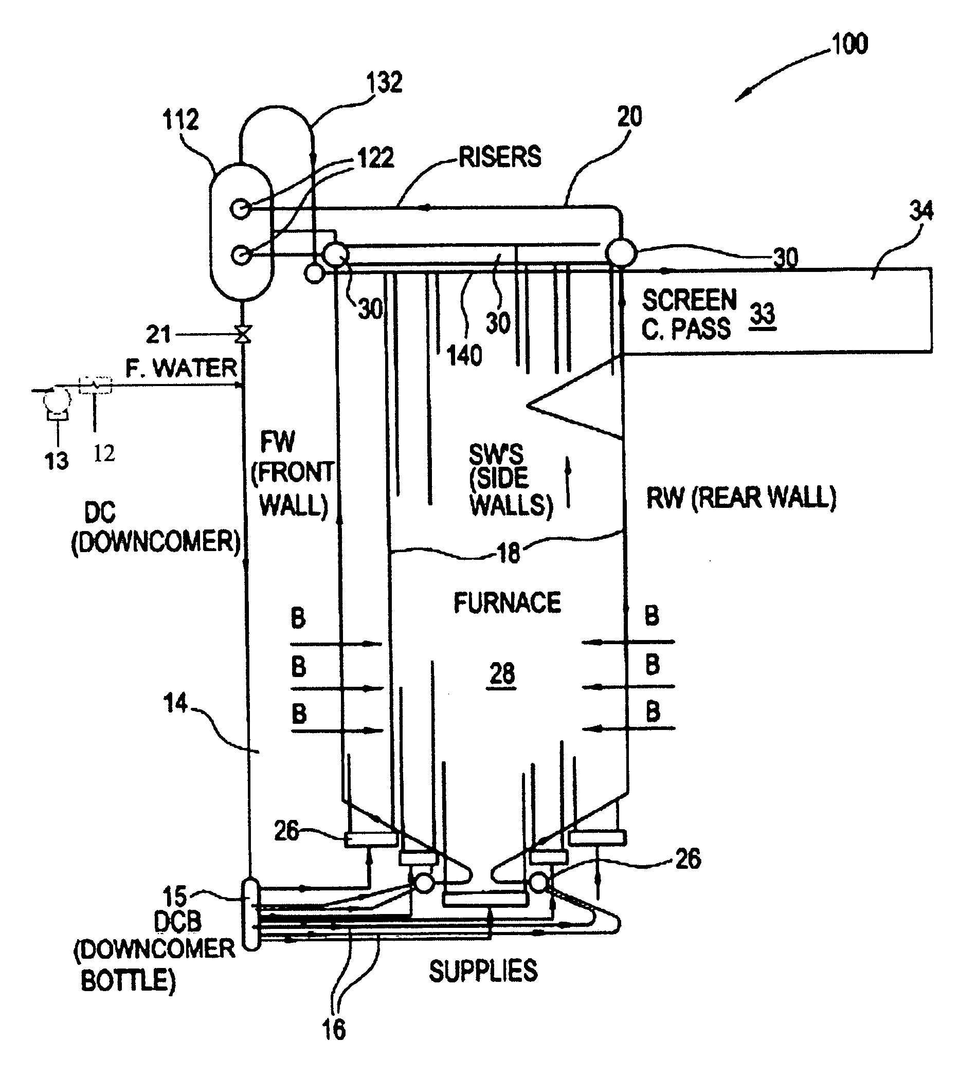
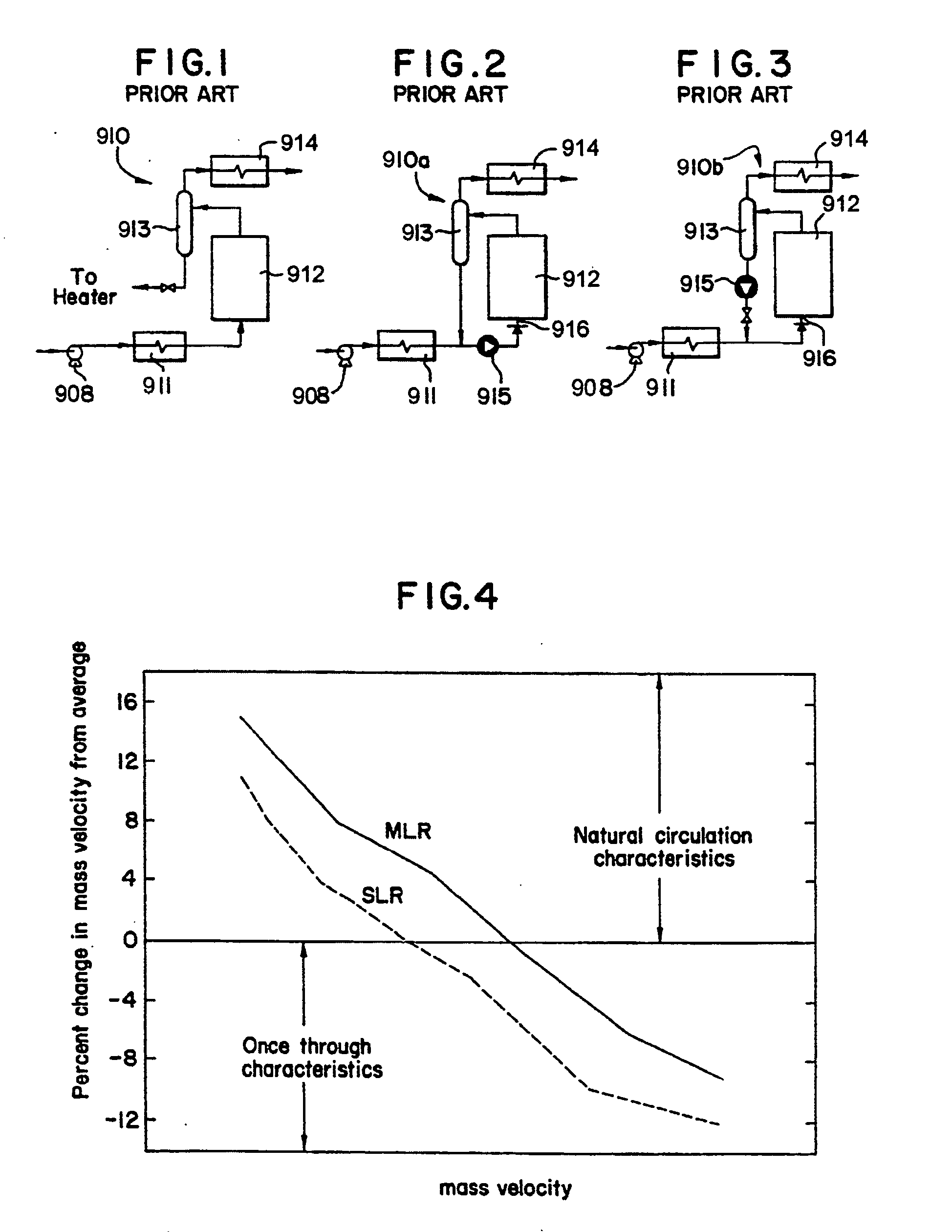
[0020]One of the advantages of this invention is that the flow characteristics of a natural circulation drum type of boiler can be utilized at low loads without the need of a circulation pump and / or orificing. The location of the valves is critical in this design for natural recirculation without using circulation pumps due to the extra pumping head that is generated by increasing the density of water at high elevations in the downcomer system. This allows for an optimized vertical tube furnace that provides the appropriate velocities across the operating load range and gives increased capability for on-off cycling, rapid load change, superior low load protection with a true natural circulation design, and lower overall furnace pressure drop than a spiral design. The present invention will not be velocity limited and therefore will provide adequate circulation across the whole load range. The present invention overcomes the issues with the higher and lower mass velocity types of once-through sliding pressure boilers. The furnace tubing for this invention will only require standard MLR tubing.

Problems solved by technology

Typically, most applications of the Benson design use spiral furnace circuitry for the evaporator due to the fact that a vertical tube evaporator design is more sensitive to upsets and nonuniform tube-to-tube heating.
The sliding pressure operation of the vertical tube once-through boiler is restricted to specific minimum load due to the flow requirements of the evaporator.
The development of a vertical tube sliding pressure once-through boiler is needed due to the higher cost of the spiral furnace design when compared to a vertical furnace design.
Until now, the major problem with the vertical tube design was due to the large heating difference between individual tubes in the furnace.
Higher flow resistance has a tendency to reduce the desired natural circulation effect.
Thermal-hydraulic problems are associated with the operational and design issues of once through boilers at reduced loads.
These design issues are partially caused by the large variation in the furnace heat distribution and often require the use of orifices and / or circulation pumps to distribute the flow to the furnace circuits to correct the circulation problem.
The pressure drop associated with a furnace design with high velocities results in less efficient boiler design.
Other circulation design concerns with once through boilers occur at lower loads due to dynamic flow stability problems.
Since the flow velocity is much lower at low loads, flow instability may occur which is undesirable for safe and reliable boiler operation.
Correction of this problem has resulted in the orificing of each individual tube in the furnace.
The orificing increases the pressure drop of the once through boiler design resulting in a less efficient boiler.
However, the cost of this new ribbed tube is much greater than the normal type of ribbed tube.

Method used


Image

  • Circulation system for sliding pressure steam generator
  • Circulation system for sliding pressure steam generator
  • Circulation system for sliding pressure steam generator

Examples


Embodiment Construction

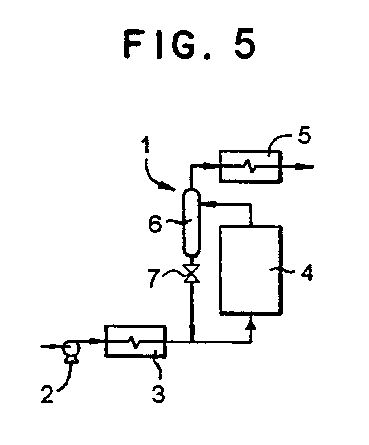
[0034]Referring now to the drawings, in which like reference numerals are used to refer to the same or similar elements, FIG. 5 shows a circulation system 1 that can be used to operate a steam generator as either a natural circulation steam generator or a sliding pressure once-through steam generator, but only one of these types of circulation systems at a time.

[0035]A boiler feed pump 2 pressurizes the system 1 and provides the entire driving head to force water through an economizer 3 for supplying heated water to the waterwall tubes of an evaporator 4 (e.g., a furnace). Preferably, the evaporator 4 has a vertical tube design. A first conduit, or system of conduits, leads from the outlet of the economizer 3 to the vertical waterwall tubes. A plurality of inlet headers (not shown) connect the end of the first conduit to the lower end of the waterwall tubes for conveying the heated water from the conduit to the waterwall tubes.

[0036]The system 1 further includes a steam utilization ...


PUM


Abstract

A steam generator circulation system is provided and includes a boiler feed pump for forcing water through an economizer, and through the waterwall tubes of an evaporator. A separator receives a mixture of steam and water and sends the steam to a steam utilization unit such as a superheater. A valve is provided below the separator. If the valve is open, the saturated water from the separator is mixed with feedwater and recirculated through the tubes of the evaporator. If the valve is closed, recirculation is terminated. At loads below the critical point, the valve below the separator system would be open and the boiler would operate like a natural circulation drum boiler. At loads above the critical point, the valve below the separator system would be closed resulting in a boiler that operates like a once-through boiler.

Description

FIELD AND BACKGROUND OF THE INVENTION [0001]The present invention relates generally to the field of steam generators and in particular to a new and useful circulation system for sliding pressure steam generators.[0002]The design of once-through boilers has been around since 1926. The design of the once-through boiler was developed by Siemens on the basis of ideas that were proposed by Mark Benson. The Benson boiler introduced the concept of sliding pressure operation for a supercritical steam pressure design (e.g., to accommodate supercritical steam pressure). In the Benson design, the boiler feed pump provides the entire driving head to force the water through the economizer, evaporator, and superheater. Water is continuously evaporated to dryness and then superheated without any steam-water separation. The circulation method is applicable to all operating pressures both supercritical and subcritical. Typically, most applications of the Benson design use spiral furnace circuitry fo...

Claims


Application Information

Patent Timeline
IPC IPC(8): F22D7/00
CPCF22B29/04F22B29/12F22B29/068
Inventor ALBRECHT, MELVIN J.
Owner THE BABCOCK & WILCOX CO
Learn More