Powered Hand Tool

a hand tool and power supply technology, applied in the field of hand tools, can solve the problems of excessive vibration, limited flexibility of flexible shaft length, and inability to provide efficient or effective power output to hand tools, and achieve the effect of reducing heat transfer

Inactive Publication Date: 2007-12-27
IBEX INDS
View PDF55 Cites 748 Cited by
  • Summary
  • Abstract
  • Description
  • Claims
  • Application Information

AI Technical Summary

Benefits of technology

[0031] Preferably, the insulation means substantially surrounds heat generating hand tool components a

Problems solved by technology

For example, a power tool which is likely to be held and operated for extended periods of time is desirably of a weight and size which does not produce or minimises stress and muscle fatigue to an operator.
Such systems however tend not to provide efficient or effective power outputs to the hand tools, with pneumatic systems requiring suitable compressors and air filtration units to enable the necessary hygiene for a pressurised air supply; with the maneuverability and location of the hand tool being determined by the length of the air supply hose.
Electrically driven flexible shaft systems may tend to cause excessive vibration, and are also stric

Method used


Image

  • Powered Hand Tool
  • Powered Hand Tool
  • Powered Hand Tool

Examples


second embodiment

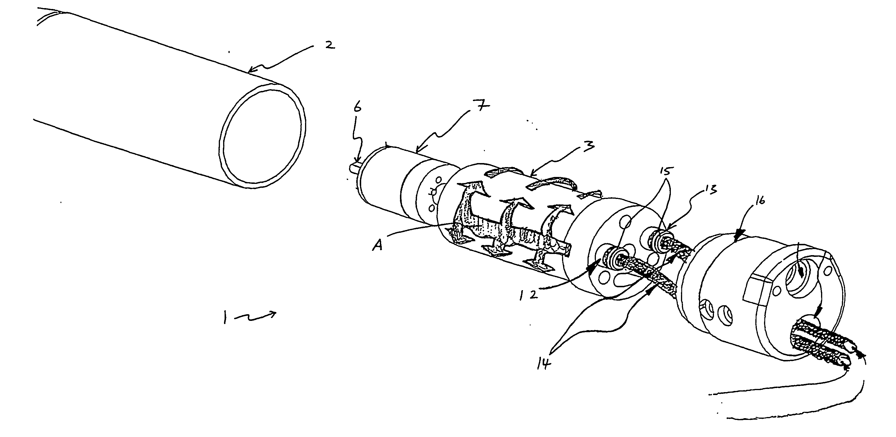
[0085] One particular example of a suitable brushless DC motor, especially suitable for the second embodiment described below would be a motor unit having dimensions 27 mm diameter, 65 mm in length; and having 4 turns of coil. It has approximately 800 r.p.m. per volt applied, and has an operating voltage of approximately 24 volts.

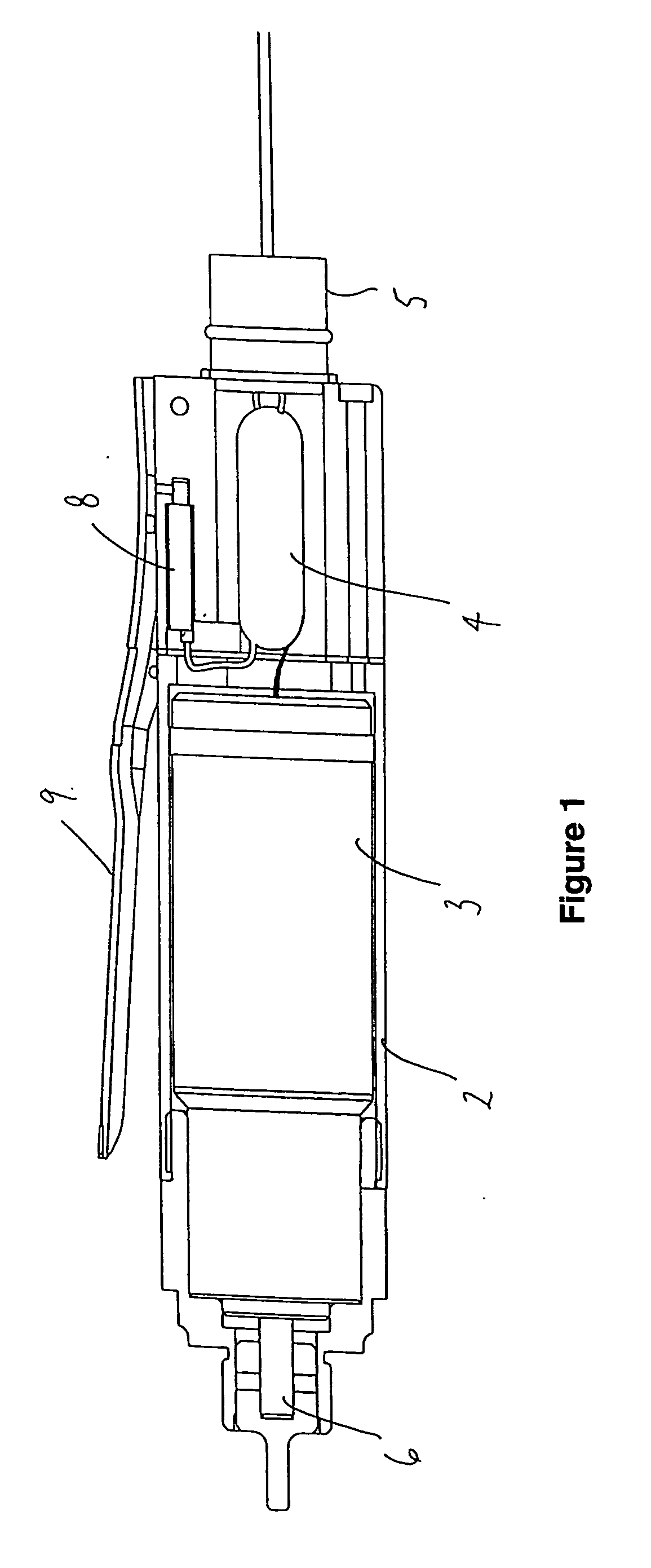
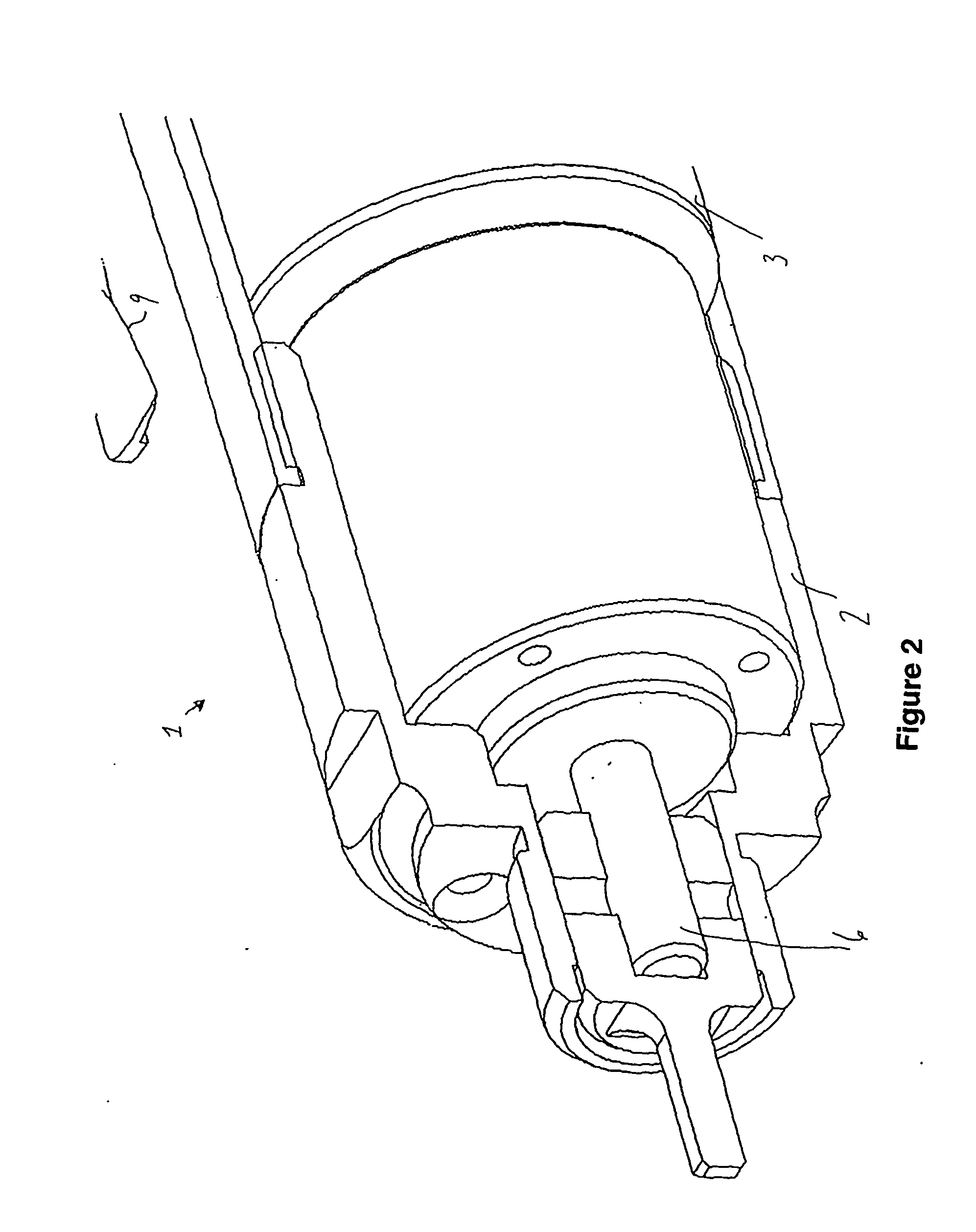
[0086] In a second embodiment of the present invention, and with reference to FIGS. 4 to 8, a hand tool 1 has a body (or housing) 2 containing a motor 3 the motor may be a brushless DC motor in which case it is able to be sealed within a motor housing. The body is configured to provide an air gap 10 about the motor 3 and between the internal surface 11 of the body 2 to thereby provide a void space about the motor. A pressurised fluid supply may be supplied to the void space via a fluid inlet port 12, ducted through the void space 10 (for example, following the flow path indicated by arrows A) by ducting means, and removed via a fluid outlet port 13. The bru...

first embodiment

[0098] The power activating switch may for example be similar to the magnetic reed switch 8 shown in the The switch design includes a ledge (or tapered step) 21 which fits over and latches to a lug 22 when the base 19 has been pushed in and then the handle 9 held flush with the body. Once in this position the biasing force of the spring 17 is transferred to the ledge (or tapered step) 21 / lug 22 interface so that the user is simply required to maintain depression of the handle 9 in order to utilise the hand tool. Desirably, once the handle has been depressed toward the body of the tool, the ledge and lug design enable minimal force by a user to hold the handle in the depressed position (and thereby in an operating mode).

[0099] Given the spring-loaded plunger mechanism, if the switch handle is released at any time, the spring will promote the plunger outwards thereby deactivating the first mechanism switch 20, cutting power to the motor and therefore stopping hand tool operation. In ...


PUM

PropertyMeasurementUnit
Temperatureaaaaaaaaaa

Abstract

The invention relates to a hand tool for use with attachments. The hand tools of the invention may be used with attachments with various speed and torque requirements. Preferred hand tools comprise a body with a brushless DC motor and means. which control the energisation of the motor. In use the brushless DC motor of the preferred hand tool is electrically supplied to drive a power output means connected to said motor. Another preferred hand tool comprises a body with a motor contained therein, a void space between an internal surface of the body and at least a part of the motor, a fluid inlet port provided and a fluid outlet port provided in or on the body, and ducting means which provides a channel for fluid supplied via the fluid inlet port to and from the void space and then on to the fluid outlet port.

Description

TECHNICAL FIELD [0001] This invention relates to a hand tool and in particular, though not solely, this invention relates to a powered hand tool for use with a variety of working end attachments with varied speed and / or torque requirements. BACKGROUND ART [0002] Powered hand tools may have a number of size, weight and motor output considerations depending upon their use. For example, a power tool which is likely to be held and operated for extended periods of time is desirably of a weight and size which does not produce or minimises stress and muscle fatigue to an operator. [0003] Operator fatigue while using power tools can lead to unnecessary accidents which are to be especially avoided in a workplace where individual and group safety is of prime importance. In the food industry, particularly the meat works industry, the trimming of meat from carcasses is performed by a variety of fixed cutting tools such as knives as well as smaller more maneuverable power hand tools. [0004] Ther...

Claims


Application Information

Patent Timeline
IPC IPC(8): B25F1/00B23D55/06B25F3/00B25F5/00B26B7/00B26B25/00H02K9/14
CPCB23D55/06B25F3/00H02K9/14B26B7/00B26B25/002B25F5/008
Inventor AVENELL, ERIC GWYN
Owner IBEX INDS
Why Eureka
Try Eureka