Full function precision welding system

Inactive Publication Date: 2007-12-27
SPENCER KEITH
View PDF14 Cites 36 Cited by
  • Summary
  • Abstract
  • Description
  • Claims
  • Application Information

AI Technical Summary

Benefits of technology

[0017]Wire Feed—Depending on the gas tungsten arc weld (GTAW) process utilized, the wire feed device may be used to feed a given amount of round metallic filler material into the weld zone. In most cases the weld wire is a drawn wire having a desired metallurgical composition necessary to yield the required mechanical strength when joining two adjacent pipe or tube segments, or to overlay the pipe or tube with a material that will increase corrosion and / or abrasion resistance.
[0018]Numerous benefits are obtained from utilization of a precision welding system according to the present invention. The benefits include the ability to locate all motors, motion feedback and other electromechanical devices at a remote location so that they are not subjected to the heat of the welding process, and therefore, do not need to be cooled. Remote placement permits the motors to be enlarged sufficiently to provide ample power while utilizing industry standard low cost assemblies. Similarly, the highly simplified mechanical design of the drive train and other mechanical components can be made sufficiently large utilizing industry standard components. As a result, a precision welding system according to the present invention is considerably more robust, and is considerably more reliable and simple to service and maintain. The weld head assembly does not include any type of motor or electrical subassembly, meaning that the system is tolerant of vibration and physical shock and can be submerged for cleaning and for radiological decontamination purposes. The modular nature of the components permits the precision welding system to be physically scaled for most any diameter of pipe or tube.

Problems solved by technology

Particular examples of confined spaces in which precision welding systems are utilized include primary cooling circuits of nuclear and fossil-fuel electric power generating plants, and fossil-fuel power boilers and heat exchangers where the need to increase heat transfer rates results in very dense pipe-to-pipe or tube-to-tube configurations which prohibit the use of conventional welding systems.
Furthermore, due to the use of natural uranium as the fuel, the reactor cannot sustain a chain reaction if the original geometry of the fuel channel is altered in any significant manner.
Nevertheless, the feeder pipes 100 are subject to erosion and corrosion that results from the constant, high temperature, high pressure flow of heavy water through the pipes.
Erosion and corrosion causes gradual thinning of the walls of the feeder pipes over time.
However, this phenomenon is predictable.
Replacement, however, has proven difficult due to the close spacing of the feeder pipes and interference from other reactor structures and components, as shown in FIGS. 4 and 5.
As a result, needless additional down time is experienced along with the additional expense incurred from cutting and re-welding feeder pipes not needing repair.
Although this practice has been utilized for decades, the configuration is limited in its application due to several fundamental features that have heretofore proven difficult to improve.
Due to their size the system is limited in the amount of power it can generate and therefore is sensitive to mechanical loads.
This results in added complexity, increased cost and decreased reliability.
Furthermore, existing devices and processes are not small enough to satisfy applications requiring small working areas due to packaging constraints encountered when the devices are mounted directly on the weld head assembly.
For the same reason, the available devices cannot be packaged in such a fashion as to be remotely deployed through or past space-limiting obstructions.
This is typically accomplished by circulating pressurized water in a jacket surrounding the heat sensitive components—adding complexity and radically reducing system reliability.
The physical size of the motors and the mechanical drive systems render it impractical to fabricate compact, highly robust precision welding systems.
Therefore, precision welding systems utilizing existing devices and processes are limited to applications that allow for the radial and axial space requirements of such systems.
Finally, existing devices and processes do not fully satisfy safety concerns, such as radiation exposure, which require that repairs be carried out with minimum radiation exposure to repair workers.

Method used


Image

  • Full function precision welding system
  • Full function precision welding system
  • Full function precision welding system

Examples


Embodiment Construction

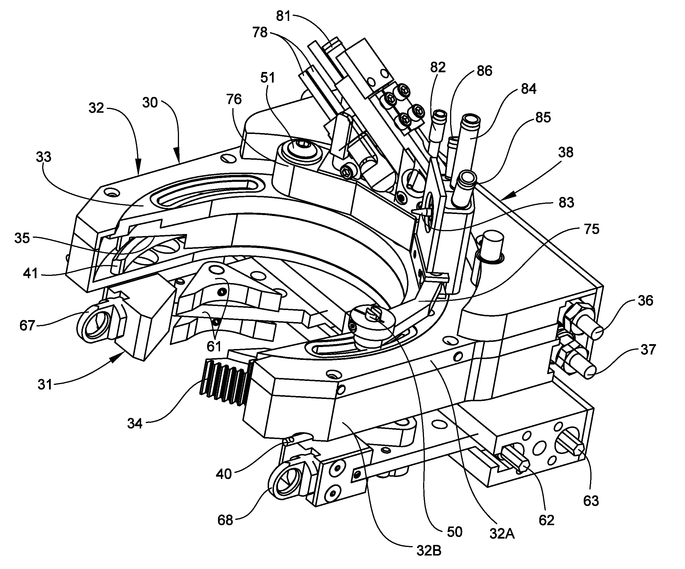
[0054]Referring now specifically to the drawings, a precision welding system according to a preferred embodiment of the invention is illustrated in FIG. 6 and indicated generally at reference numeral 10. The welding system 10 includes a motor housing 11, a weld head assembly 12 remote from the motor housing 11, and an insertion tube 13 interconnecting the weld head assembly and motor housing. Housing supports 14 and 16 are positioned on opposing ends of the motor housing 11 to allow the welding system 10 to rotate about a longitudinal axis. The supports 14 and 16 are rotatably attached to a platform 17 that allows the welding system 10 to move, in addition to rotating, in X, Y, and Z directions. As shown, the combination of the supports 14, 16 and platform 17 allow the weld head assembly 12 to be positioned for insertion into a confined space between pipes, for example feeder pipes 18 of a CANDU reactor. As illustrated in FIGS. 7 and 8, the weld head assembly 12 may be inserted betw...


PUM

PropertyMeasurementUnit
Distanceaaaaaaaaaa
Circumferenceaaaaaaaaaa

Abstract

A welding system for performing a welding process on a pipe in a confined space includes a motor housing, a weld head assembly and an insertion tube that extends between the motor housing and the weld head assembly with the weld head assembly remote from the motor housing. The motor housing is supported on a platform for rotational and translational movement of the weld head assembly and houses a motor for positioning the weld head assembly relative to the pipe. The weld head assembly includes a clamp assembly for attaching the weld head assembly to the pipe and a weld tool assembly mounted adjacent the clamp assembly for welding the pipe. An arc length gear and a travel gear adjust the distance between a torch assembly and the pipe and adjust the location of the torch assembly around the pipe when the weld head assembly is attached to the pipe.

Description

CROSS REFERENCE TO RELATED APPLICATION[0001]This application claims the benefit of U.S. Provisional Application No. 60 / 803,103, filed May 24, 2006.FIELD OF THE INVENTION[0002]This invention relates generally to welding systems, and more particularly to precision welding systems for use in welding pipes, tubes and similar structures in confined spaces.BACKGROUND OF THE INVENTION[0003]Precision welding systems are utilized for welding pipes, tubes and similar structures in confined spaces. Particular examples of confined spaces in which precision welding systems are utilized include primary cooling circuits of nuclear and fossil-fuel electric power generating plants, and fossil-fuel power boilers and heat exchangers where the need to increase heat transfer rates results in very dense pipe-to-pipe or tube-to-tube configurations which prohibit the use of conventional welding systems. The invention in its various aspects is described and explained with reference to a nuclear reactor type...

Claims


Application Information

Patent Timeline
IPC IPC(8): G21C17/00
CPCB23K9/0286B23K2201/06G21C17/017G21Y2002/203G21Y2002/204G21Y2004/504G21Y2002/40G21Y2002/501G21Y2004/30G21Y2004/501G21Y2002/304B23K2101/06Y02E30/30
Inventor SPENCER, KEITHPOWELL, BRADLEY
Owner SPENCER KEITH
Why Eureka
Try Eureka