Infrared sensor

a sensor and infrared technology, applied in the field of infrared sensors, can solve the problems of poor selectivity of these sensors, decreased sensor performance, lack of specific analyte selectivity, etc., and achieve the effect of minimizing the probability of false alarms and more accurate detection

Inactive Publication Date: 2008-01-10
THOMAS ROSS C +2
View PDF32 Cites 33 Cited by
  • Summary
  • Abstract
  • Description
  • Claims
  • Application Information

AI Technical Summary

Benefits of technology

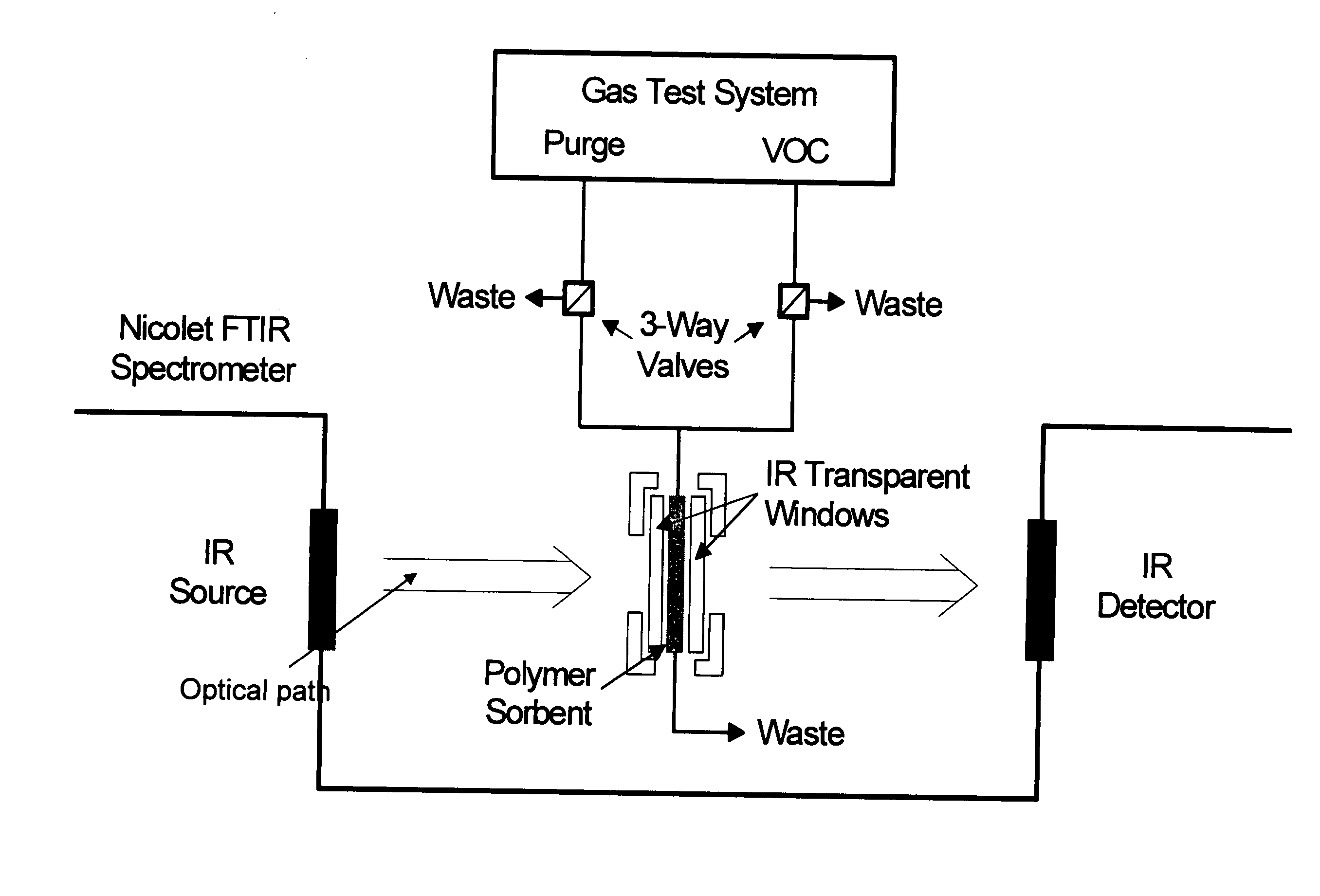
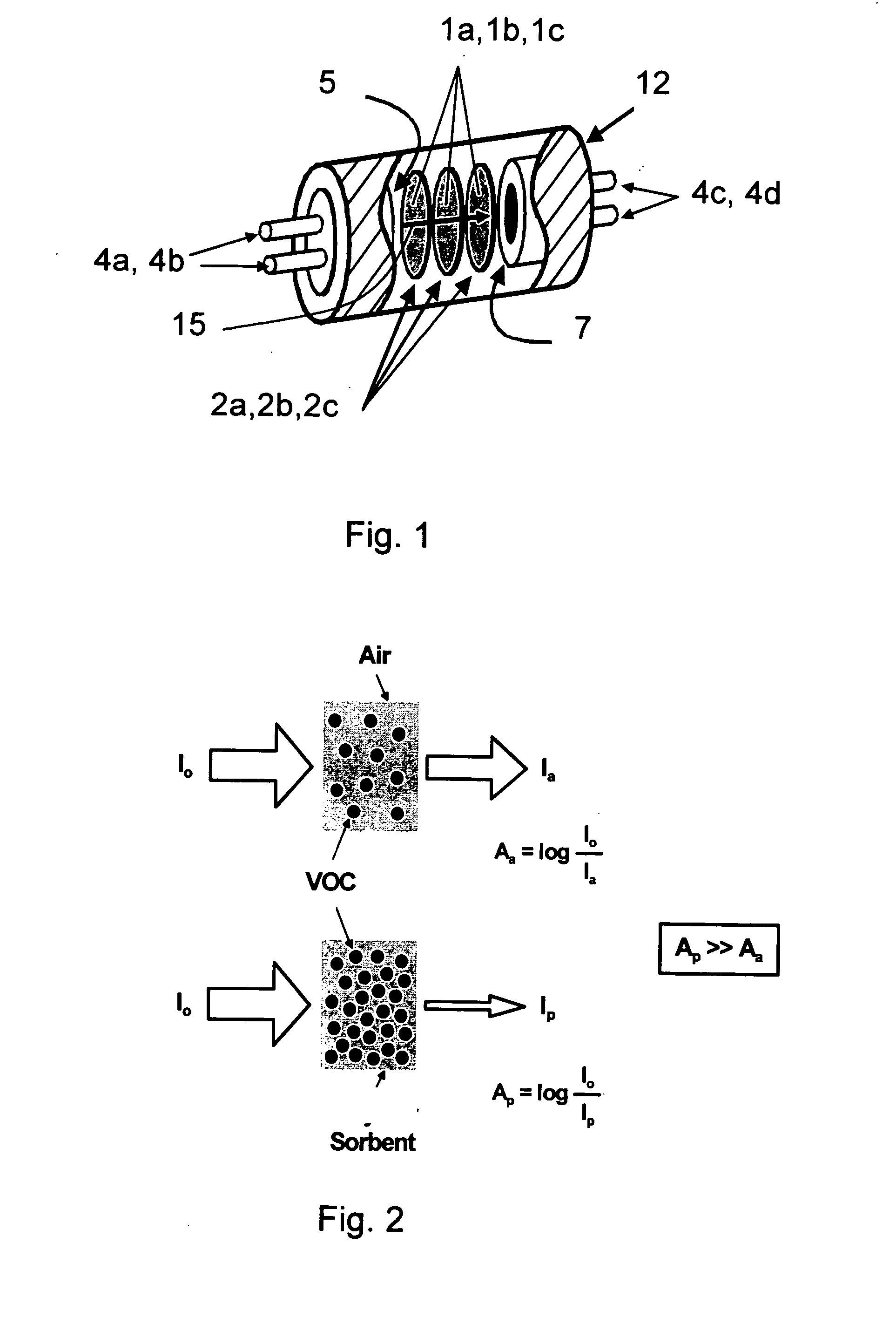
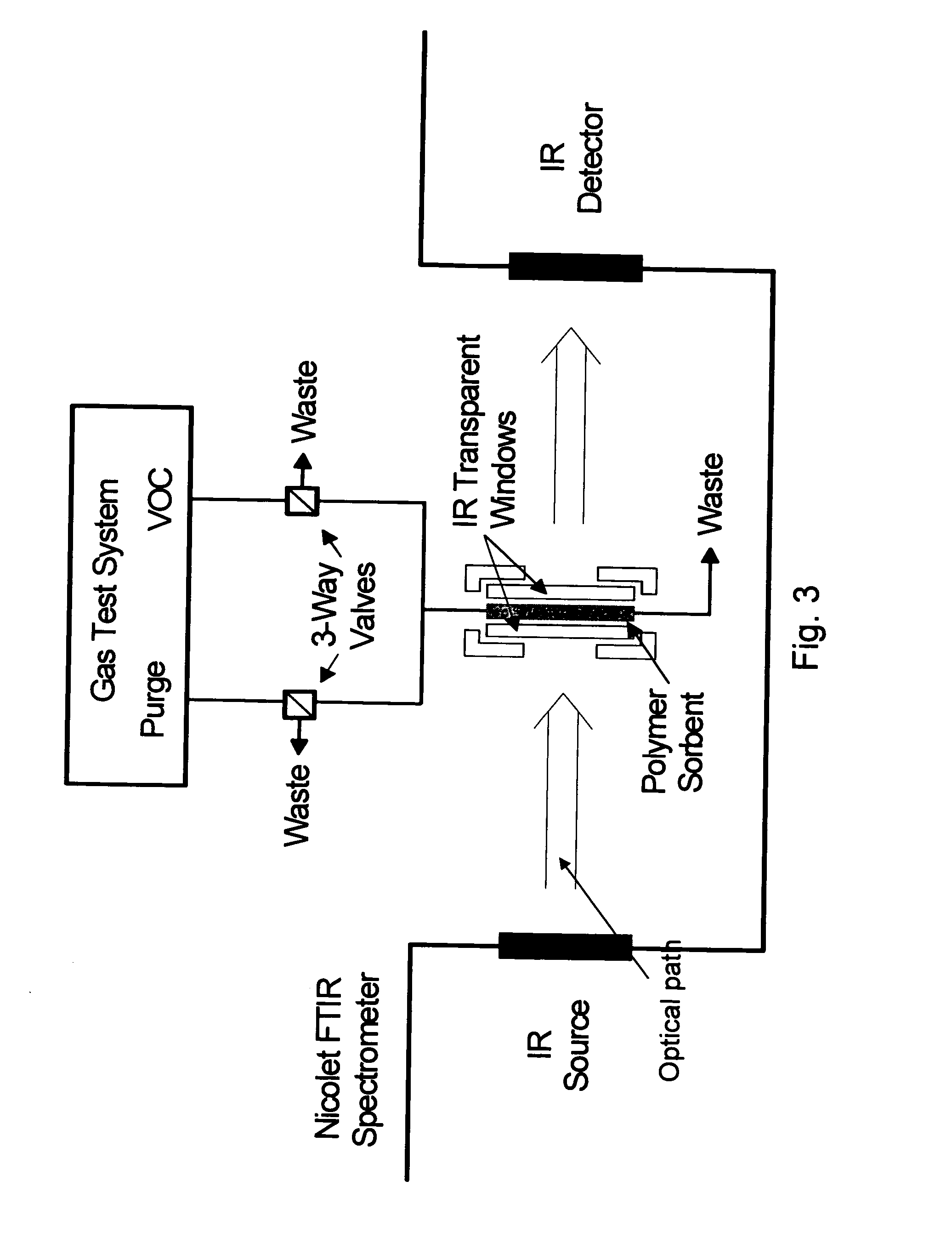
[0032] In a specific embodiment the IR detector is configured to monitor IR absorption at multiple wavelengths as well as to monitor the ratio of IR absorbance between two or more wavelengths. More specifically, the IR detector is configured to monitor the ratio (At/Ar) of IR absorbance at one or more wavelengths characteris

Problems solved by technology

One of the main limitations with most such chemical sensors is their lack of selectivity for specific analytes, because, for the most part, they rely upon indirect measurement methods.
The data are reported to indicate that certain organophosphorous compounds undergo decomposition on the metal oxide surfaces at temperatures above 200° C. which lead to decreased sensor performance.
While a number of conductometric oxide-based sensors have been described several limitations exist.
In addition, the selectivity of these sensors is poor because any gaseous species that

Method used


Image

  • Infrared sensor
  • Infrared sensor
  • Infrared sensor

Examples


example 1

Polymer Thin-Film IR Sensors

Materials

[0113] Unless otherwise noted, all chemicals were purchased from Aldrich. A formulation of a fluorinated epoxy (FE), which was designed to enhance the response of organophosphorus-based CWAs, was synthesized as described below from commercially available materials. Diglycidyl ether of bisphenol F (DGEBF) was reacted with the diol α,α,α′,α′-tetrakis(trifluoromethyl)-1,4-benzenedimethanol in refluxing 1-butanol, in the presence of a catalytic amount of tributylamine and varying mole percentages of a reactive diluent (styrene oxide) to reduce the crosslinking density of the product for improved properties. Use of from about 25 to about 55 mole percent of styrene oxide afforded soluble, processable materials.

[0114] A formulation of poly-vinylchloride-co-vinylacetate-co-vinylalcohol (PVCAA) (from Aldrich Chemicals) and diethylene glycol adipate (DEGA) from Ohio Valley Specialty Chemicals was used to enhance the permeability of ERCs employing nitro...

example 2

Metal Oxide Sorbent IR Sensors

Film Preparation:

[0126] To prepare a film, a metal oxide was suspended in alcohol. For example, a suspension of 0.1 g TiO2 (anatase, Alfa Aesar, 99.9%) in 2 mL isopropanol was prepared. The suspension was sonicated for 5 minutes to ensure a through dispersion of the metal oxide (e.g., TiO2) in the solvent. A portion of the suspension was collected with a pipette, applied to the surface of an IR transparent substrate (a KBr disc), and allowed to evaporate. The thickness of this film was determined to be 25 μm based on a cross section examined by scanning electron microscopy (SEM) although various thicknesses can be achieved (0.1-100 microns) by varying the concentration of metal oxide in the suspension or altering the deposition method. A 0.025 g TiO2 in 2 mL isopropanol suspension was used to form a ca. 6 micron thick sorbent layer to detect 100 ppb DMMP. FIG. 10 shows IR absorbance (the P—O stretch) of DMMP adsorbed into the anatase TiO2 film contac...


PUM


Abstract

Devices, materials and methods for the detection of one or more target analytes, particularly volatile organic compounds (VOCs) in air or other gases. Point sensors and sensor arrays for the detection of one or more of such analytes in air or other gases. Sensors employ the detection of IR absorption of wavelengths characteristic of a target analyte or a class of target analytes to detect the presence of and/or measure the concentration of one or more target analytes in air or other gases. Sensors employ sorbent layers into which one or more of the target analytes are adsorbed from the air or other gases to be analyzed. Preferred sorbent layers comprise polymer sorbents, metal oxide sorbents or mixtures thereof.

Description

CROSS-REFERENCE TO RELATED APPLICATIONS [0001] This application claims priority to U.S. provisional application Ser. No. 60 / 622,873, filed Oct. 27, 2004, which is incorporated by reference in its entirety herein.STATEMENT REGARDING U.S. GOVERNMENT FUNDING [0002] This invention was made under funding from the United States Government through the U.S. Marine Corp System Command under SBIR contract nos. M67854-02-C-3087 and M67854-04-C-3104 and the U.S. Army CECOM Night Vision and Electronic Sensors Directorate under SBIR contract no. DAAB07-01-C-L852. The United States government has certain rights in this invention.BACKGROUND OF THE INVENTION [0003] Over the past several years, a considerable effort has been spent developing new and improved chemical sensors for detecting the presence of chemical warfare agents (CWAs) and explosive related chemicals (ERCs). This invention relates to methods, devices and materials useful for infrared (IR) detection of organic species, particularly vol...

Claims


Application Information

Patent Timeline
IPC IPC(8): G01N21/00
CPCG01N1/2214G01N2001/022G01N21/3504
Inventor THOMAS, ROSS C.CARTER, MICHAEL T.TRIMBOLI, JOSEPH ANTHONY
Owner THOMAS ROSS C
Why Eureka
Try Eureka