Pearlitic steel rail excellent in wear resistance and ductility and method for producing same

a technology of ductility and wear resistance, applied in the field of pearlitic steel rails, can solve the problems of rail breakage, insufficient wear resistance, and increased wear at the gauge corner and the head side portions of the rail laid on a curved track, and achieve excellent wear resistance and ductility

Inactive Publication Date: 2008-01-17
NIPPON STEEL CORP
View PDF0 Cites 26 Cited by
  • Summary
  • Abstract
  • Description
  • Claims
  • Application Information

AI Technical Summary

Benefits of technology

[0013] In the aforementioned situation, a pearlitic steel rail excellent in wear resistance and ductility and a production method thereof are looked for, to make it possible, in a rail of pearlite structure having a high carbon content, to realize: a superior wear resistance at the head portion of the rail; a high resistance to rail breakage by enhancing ductility; the prevention of the formation of pro-eutectoid cementite structures by optimizing cooling conditions; and, in addition to those, the uniformity in material characteristics in the longitudinal direction of the rail and the suppression of decarburization at the outer surface of the rail.
[0014] The present invention provides a pearlitic steel rail excellent in wear resistance and ductility and a production method thereof, wherein, in a rail used for a heavy load railway, the wear resistance and ductility required of the railhead portion are enhanced, the resistance to rail breakage is improved in particular, and the fracture resistance of the web, base and base toe portions of the rail is improved by preventing pro-eutectoid cementite structures from forming.
[0015] Further, the present invention provides a high-efficiency and high-quality pearlitic steel rail, wherein: cracking and breakage during hot rolling are prevented by optimizing the maximum heating temperature and the retention time at a reheating process in the event of hot-rolling a high-carbon steel bloom (slab) for rail rolling; and, in addition, the deterioration of wear resistance and fatigue strength is suppressed by controlling decarburization in the outer surface layer of the rail.

Problems solved by technology

Specifically, wear at the gauge corner and the head side portions of a rail laid on a curved track increases drastically and the fact has come to be viewed as a problem from the viewpoint of the service life of a rail.
However, there is a problem in that wear resistance is insufficient and rail breakage is likely to occur when the rail is used for a heavy load railway since ductility is low.
However, ductility is prone to deteriorate and, therefore, resistance to breakage of a rail is low as the carbon content thereof is higher than that of a presently used eutectoid carbon-containing steel.
Further, there is another problem in that segregation bands, where carbon and alloying elements are concentrated, are likely to form at the center portion of a casting at the stage of the cast of molten steel, pro-eutectoid cementite forms in a great amount along the segregation bands especially at the web portion, which is indicated by the reference numeral 5 in FIG. 1, of a rail after rolling, and the pro-eutectoid cementite serves as the origin of fatigue cracks or brittle cracks.
Furthermore, when a heating temperature is inadequate in a reheating process for hot-rolling a bloom (slab) to be rolled, the bloom (slab) is in a molten state partially, cracks develop and, as a consequence, the bloom (slab) breaks during hot rolling or cracks remain in the rail after finish hot rolling, and therefore the product yield deteriorates.
What is more, another problem is that, in some retention times at a reheating process, decarburization is accelerated in the outer surface layer of a bloom (slab), hardness lowers, caused by the decrease of a carbon content in pearlite structures in the outer surface layer of a rail after finish hot rolling and, therefore, wear resistance at the head portion of the rail deteriorates.
However, despite the proposed technologies, the ductility and toughness of rails have been insufficient in cold regions where the temperature falls below the freezing point.
What is more, even when such average size of block grains in pearlite structures as described above is made still finer in an attempt to enhance the ductility and toughness of rails, it has been difficult to thoroughly suppress rail breakage in cold regions.
Further, in the rails proposed in the cases 4) and 5) above, there is a problem in that, in some rolling lengths and rolling end temperatures of rails, the uniformity of the material quality of the rails in the longitudinal direction and the ductility of the head portions thereof cannot be secured.
On top of that, although it is possible to secure the hardness of pearlite structures at head portions and suppress the formation of pro-eutectoid cementite structures at web portions by applying accelerated cooling to the head and web portions of rails, it has still been difficult to suppress the formation of pro-eutectoid cementite structures, which serve as the starting points of fatigue cracks and brittle cracks, at the base and base toe portions of the rails, even when the heat treatment methods disclosed above are employed.
Furthermore, at a web portion too, there are still other problems in that: pro-eutectoid cementite structures are likely to form because the segregation bands of various alloying elements remain; and, additionally, the temperature of the web portion is low at the end of hot rolling.
Therefore, an additional problem has been that it is impossible to completely prevent the fatigue cracks and brittle cracks originating at base toe and web portions.
What is more, in the rail disclosed in the case 6) above, though a technology of making the average size of block grains in pearlite structures fine in a hyper-eutectoid steel in an attempt to improve the ductility and toughness of a rail is disclosed, it has been difficult to thoroughly suppress the occurrence of rail breakage in cold regions.

Method used


Image

  • Pearlitic steel rail excellent in wear resistance and ductility and method for producing same
  • Pearlitic steel rail excellent in wear resistance and ductility and method for producing same
  • Pearlitic steel rail excellent in wear resistance and ductility and method for producing same

Examples


example 1

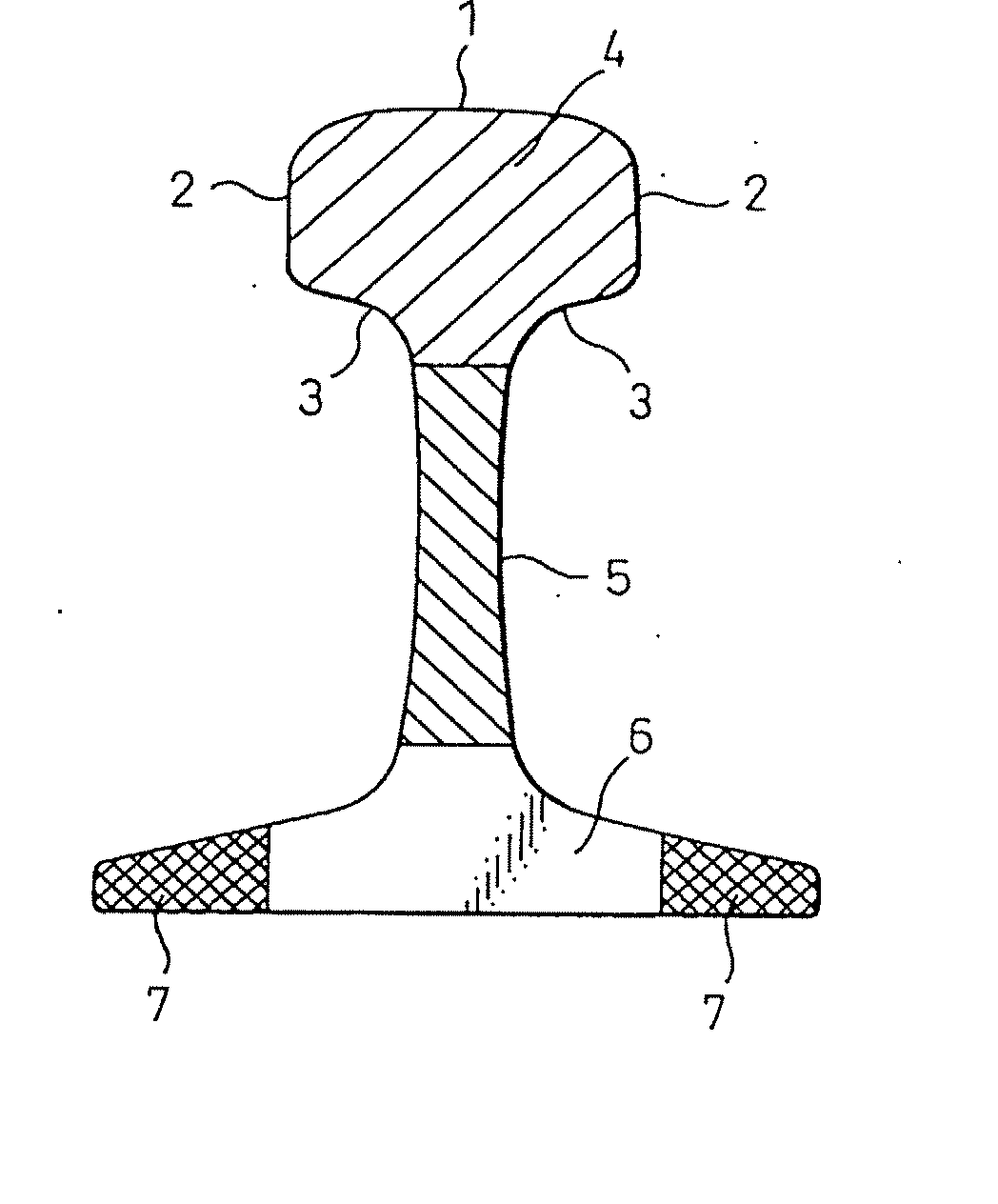
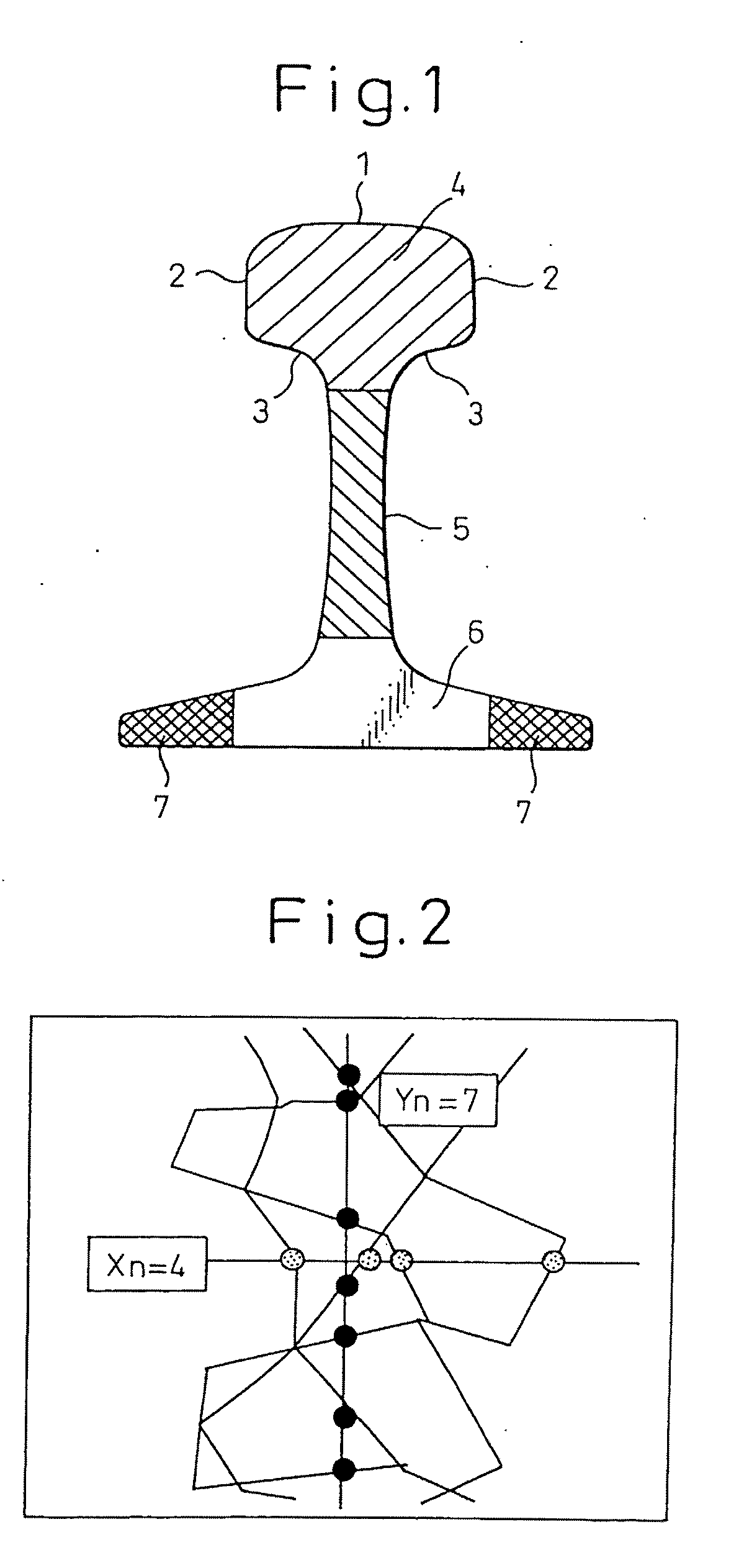
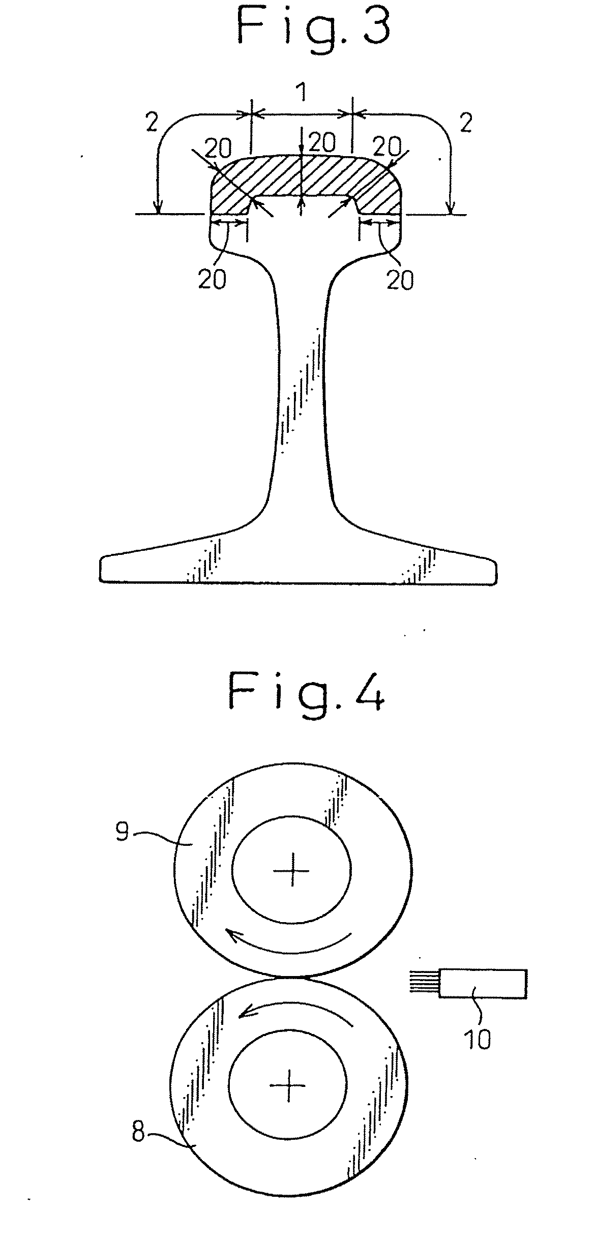
[0232] Table 1 shows, regarding each of the steel rails according to the present invention, chemical composition, hot rolling and heat treatment conditions, the microstructure of a head portion at a depth of 5 mm from the surface thereof, the number and the measurement position of pearlite blocks having grain sizes in the range from 1 to 15 μm, and the hardness of a head portion at a depth of 5 mm from the surface thereof. Table 1 also shows the amount of wear of the material at a head portion after 700,000 repetition cycles of Nishihara wear test are imposed under the condition of forced cooling as shown in FIG. 4, and the result of tensile test at a head portion. In FIG. 4, reference numeral 8 indicates a rail test piece, 9 a counterpart wheel piece, and 10 a cooling nozzle.

[0233] Table 2 shows, regarding each of the comparative steel rails, chemical composition, hot rolling and heat treatment conditions, the microstructure of a head portion at a depth of 5 mm from the surface th...

example 2

[0264] Table 3 shows, regarding each of the steel rails according to the present invention, chemical composition, hot rolling and heat treatment conditions, the microstructure of a head portion at a depth of 5 mm from the surface thereof, the number and the measurement position of pearlite blocks having grain sizes in the range from 1 to 15 μm, and the hardness of a head portion at a depth of 5 mm from the surface thereof. Table 3 also shows the amount of wear of the material at a head portion after 700,000 repetition cycles of Nishihara wear test are imposed under the condition of forced cooling as shown in FIG. 4, and the result of tensile test at a head portion.

[0265] Table 4 shows, regarding each of the comparative steel rails, chemical composition, hot rolling and heat treatment conditions, the microstructure of a head portion at a depth of 5 mm from the surface thereof, the number and the measurement position of pearlite blocks having grain sizes in the range from 1 to 15 μm,...

example 3

[0281] The same tests as in Examples 1 and 2 were carried out using the steel rails of Example 2 shown in Table 3 and changing the time period from the end of rolling to the beginning of accelerated cooling and the hot rolling conditions as shown in Table 6.

[0282] As is clear from Table 6, total elongation was further improved in the cases where the time periods from the end of rolling to the beginning of accelerated cooling were not longer than 200 sec., 2 or more passes of the finish hot rolling were applied, and the times between rolling passes were not longer than 10 sec.

TABLE 6Time fromend of hotrolling toRailbeginningHot rolling conditionslengthof3Time2TimeTimeRollingClassificationat hotacceleratedpassesbetweenpassesbetween1 passbetweenendofrollingcoolingtopassestopassestopassesFinaltemperaturerailSymbolSteel(m)(sec)final %secfinal %secfinal %secpass %° C.Invented5523198198—6980rail5629155158—89805729155158—98705829155158—2062199805931165156—89606032165135888310980613316515...


PUM

PropertyMeasurementUnit
temperatureaaaaaaaaaa
grain sizesaaaaaaaaaa

Abstract

The present invention is: a pearlitic steel rail excellent in wear resistance and ductility, characterized in that, in a steel rail having pearlite structure containing, in mass, 0.65 to 1.40% C, the number of the pearlite blocks having grain sizes in the range from 1 to 15 μm is 200 or more per 0.2 mm2 of an observation field at least in a part of the region down to a depth of 10 mm from the surface of the corners and top of the head portion; and a method for producing a pearlitic steel rail excellent in wear resistance and ductility, characterized by, in the hot rolling of said steel rail, applying finish rolling so that the temperature of the rail surface may be in the range from 850° C. to 1,000° C. and the sectional area reduction ratio at the final pass may be 6% or more, and then applying accelerated cooling to the head portion of said rail at a cooling rate in the range from 1 to 30° C. / sec. from the austenite temperature range to at least 550° C.

Description

TECHNICAL FIELD [0001] The present invention relates to: a pearlitic steel rail that is aimed at improving wear resistance at the head portion of a steel rail for a heavy-load railway, enhancing resistance to breakage of the rail by improving ductility through controlling the number of fine pearlite block grains at the head portion of the rail, and preventing the toughness of the web and base portions of the rail from deteriorating by reducing the formation of pro-eutectoid cementite structures at these portions; and a method for efficiently producing a high-quality pearlitic steel rail by optimizing the heating conditions of a bloom (slab) for said rail, thus preventing cracking and breakage during hot rolling, and suppressing decarburization in the outer surface layer of the bloom (slab). BACKGROUND ART [0002] Overseas, in heavy-load railways, attempts have been made to increase the speed and loading weight of a train to improve the efficiency of railway transportation. Such an im...

Claims


Application Information

Patent Timeline
Patent Type & Authority Applications(United States)
IPC IPC(8): C21D9/04C21D8/00C22C38/00C22C38/02C22C38/04C22C38/18
CPCC21D8/00C21D8/005C21D9/04C22C38/18C22C38/002C22C38/02C22C38/04C21D2211/009
Inventor UEDA, MASAHARUMATSUSHITA, KOICHIROFUJITA, KAZUOIWANO, KATSUYAUCHINO, KOICHIMOROHOSHI, TAKASHIKOBAYASHI, AKIRA
Owner NIPPON STEEL CORP
Why Eureka
Try Eureka