Method for Soft Error Modeling with Double Current Pulse

a technology of double current pulse and logic circuit, which is applied in error detection/correction, program control, instruments, etc., can solve the problems of large number of cells, soft error may occur, and require complicated connections between cells

Inactive Publication Date: 2008-01-17
GLOBALFOUNDRIES INC
View PDF5 Cites 17 Cited by
  • Summary
  • Abstract
  • Description
  • Claims
  • Application Information

AI Technical Summary

Benefits of technology

[0013]It is therefore one object of the present invention to provide an improved method of analyzing soft errors that arise in a logic circuit.
[0014]It is another object of the present invention to provide such a method having improved accuracy in simulating a device upset.
[0015]It is yet another object of the present invention to provide a method of modeling soft errors in a logic circuit which can take into account asymmetric resistances between the source and drain of a device.

Problems solved by technology

An IC may include a very large number of cells and require complicated connections between the cells.
For example, a soft error may occur when an alpha particle hits the diffusion regions of a metal-oxide semiconducting (MOS) transistor of a logic circuit and produces a charge that leads to a faulty transition.
A change in the state of a device caused by radiation or electrostatic discharge will only generate an error in the logic circuit if it propagates to a latch or storage element prior to the clock arrival (sampling) time.
Nevertheless, many SEUs lead to soft errors in IC chips and computer systems, and the soft error rate (SER) associated with combinational logic is steadily growing.
While field solvers provide useful analytical results, they are very complex to set up and computationally intensive to carry out.
Circuit simulators such as SPICE are straightforward and fairly quick to run, but they still have significant drawbacks in modeling the circumstances of soft errors.
The choice of where and how to inject the current pulse affects simulation accuracy, and if the simulation is not set up properly the results can be inaccurate.
It is also impossible to adjust the simulation to take into consideration certain variations in device fabrication such as different source and drain resistances.

Method used


Image

  • Method for Soft Error Modeling with Double Current Pulse
  • Method for Soft Error Modeling with Double Current Pulse
  • Method for Soft Error Modeling with Double Current Pulse

Examples


Embodiment Construction

)

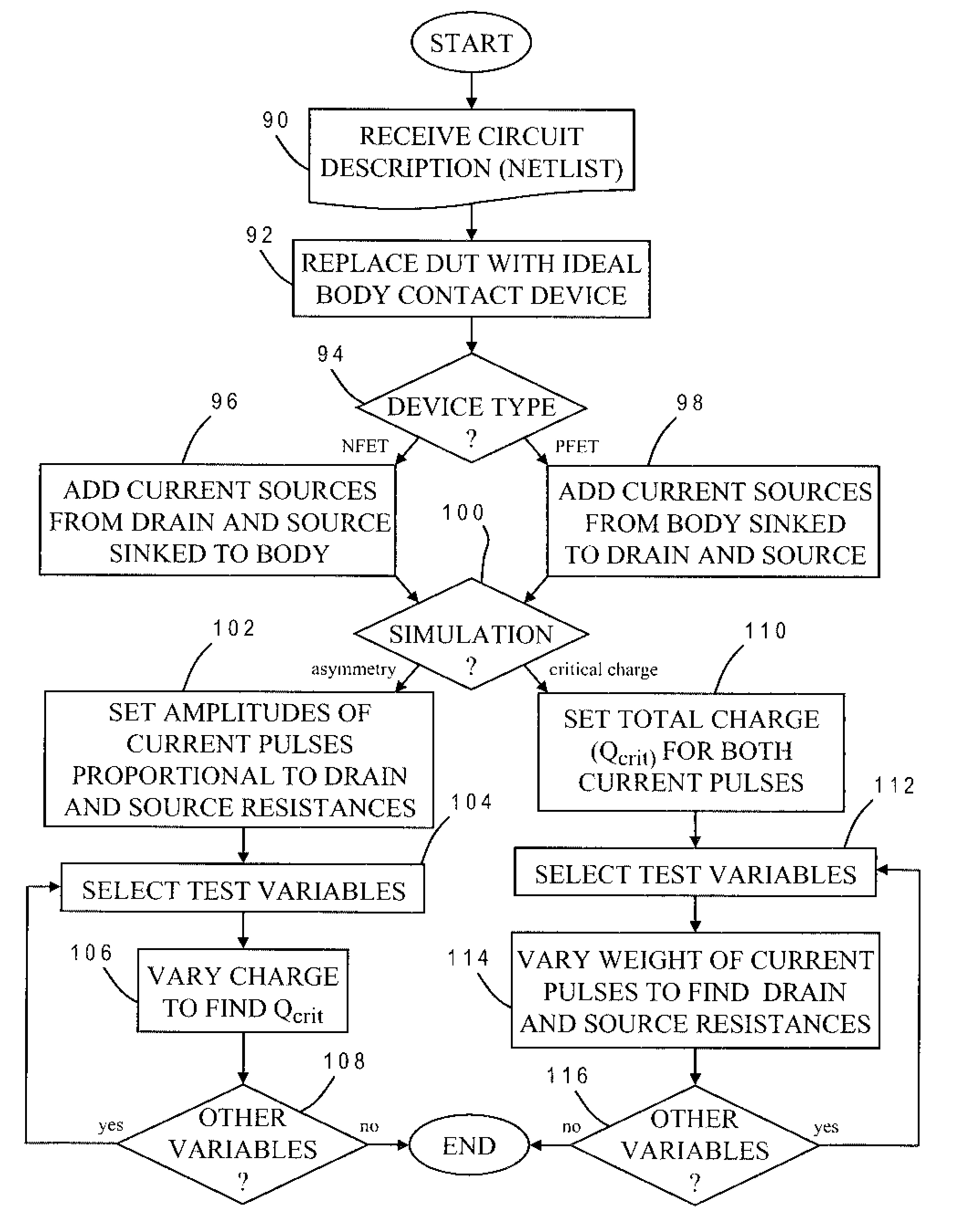
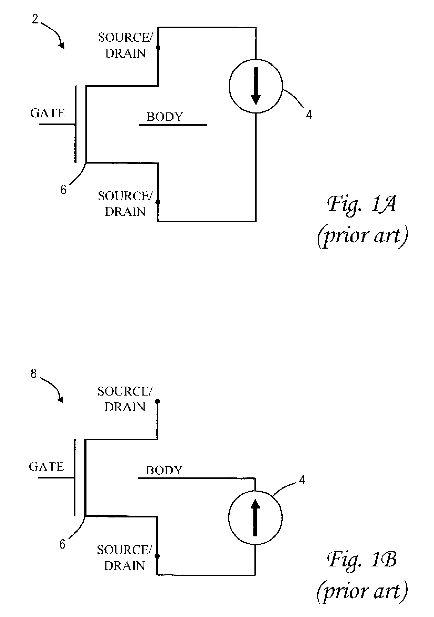
[0026]The present invention provides a novel method for modeling soft errors in logic circuits, and is generally applicable to any type of IC design including general-purpose microprocessors, memory units or special-purpose circuitry, although it is particularly suited for analyzing single event upsets in silicon-on-insulator (SOI) devices. The method may be implemented as part of a physical synthesis process which optimizes placement, timing, power consumption, crosstalk effects or other design parameters. As explained more fully below, an exemplary embodiment of the present invention uses a two current pulse mechanism for exemplifying a flood of carriers in the body and a source / drain of the device.

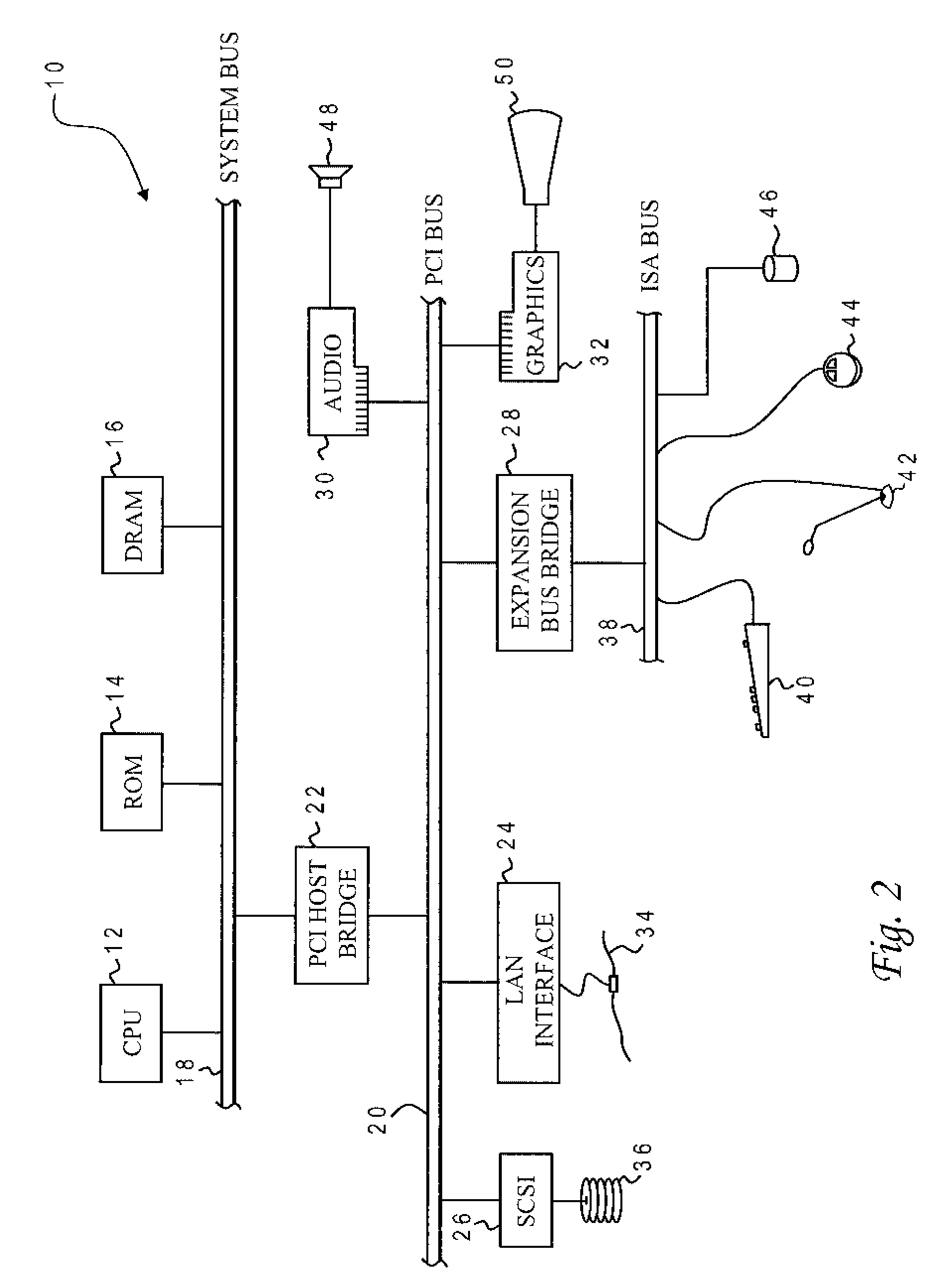
[0027]With reference now to the figures, and in particular with reference to FIG. 2, there is depicted one embodiment 10 of a computer system programmed to carry out soft error modeling in accordance with one implementation of the present invention. System 10 includes a central process...


PUM


Abstract

A method of modeling soft errors in a logic circuit uses two separate current sources inserted at the source and drain of a device to simulate a single event upset (SEU) caused by, e.g., an alpha-particle strike. In an nfet implementation the current flows from the source or drain toward the body of the device. Current waveforms having known amplitudes are injected at the current sources while simulating operation of the logic circuit and the state of the logic circuit is determined from the simulated operation. The amplitudes of the current waveforms can be independently adjusted. The simulator monitors the state of device and makes a log entry when a transition occurs. The process may be repeated for other devices in the logic circuit to provide an overall characterization of the susceptibility of the circuit to soft errors.

Description

STATEMENT REGARDING FEDERALLY SPONSORED RESEARCH OR DEVELOPMENT[0001]This invention was made with Government support under DARPA, NBCH3039004. THE GOVERNMENT HAS CERTAIN RIGHTS IN THIS INVENTION.BACKGROUND OF THE INVENTION[0002]1. Field of the Invention[0003]The present invention generally relates to the design and testing of semiconductor chips and integrated circuits, and more particularly to a method of modeling soft errors in a logic circuit that arise from, e.g., an alpha-particle strike.[0004]2. Description of the Related Art[0005]Integrated circuits are used for a wide variety of electronic applications, from simple devices such as wristwatches, to the most complex computer systems. A digital microelectronic integrated circuit (IC) chip can generally be thought of as a collection of logic cells with electrical interconnections between the cells, formed on a semiconductor substrate (e.g., silicon). An IC may include a very large number of cells and require complicated connecti...

Claims


Application Information

Patent Timeline
Patent Type & Authority Applications(United States)
IPC IPC(8): G06F17/50
CPCG01R31/31816G06F17/5036G01R31/318357G06F30/367
Inventor KLEINOSOWSKI, AJOLDIGES, PHILIP J.SOLOMON, PAUL M.WILLIAMS, RICHARD Q.
Owner GLOBALFOUNDRIES INC
Why Eureka
Try Eureka