[0021]
Work recovery is another feature of a highly efficient liquefier. Gas refrigerant compression is very work intensive and is normally done near ambient temperature. Gas refrigerant expansion is normally done in a device called an expander at cryogenic temperatures. Besides providing cooling of the refrigerant, it can be a means to recover a portion of work of compression4. The imbalance of work input in the compressor and
recovery in an expander in a conventional gas liquefier is a fundamental limitation to its efficiency. The present invention uniquely provides distributed compression in all AGRR stages at temperatures from near
room temperature to near cryogen
liquefaction temperatures and simultaneously recovers work from distributed expansion at temperatures from near
room temperature to cryogenic temperatures. This feature makes the AGRL design inherently more efficient than conventional liquefiers. 4 Isentropic expansion of a gaseous refrigerant from
high pressure to low pressure cools the refrigerant and provides
work output. This work can be used to offset the work of compression of the refrigerant.
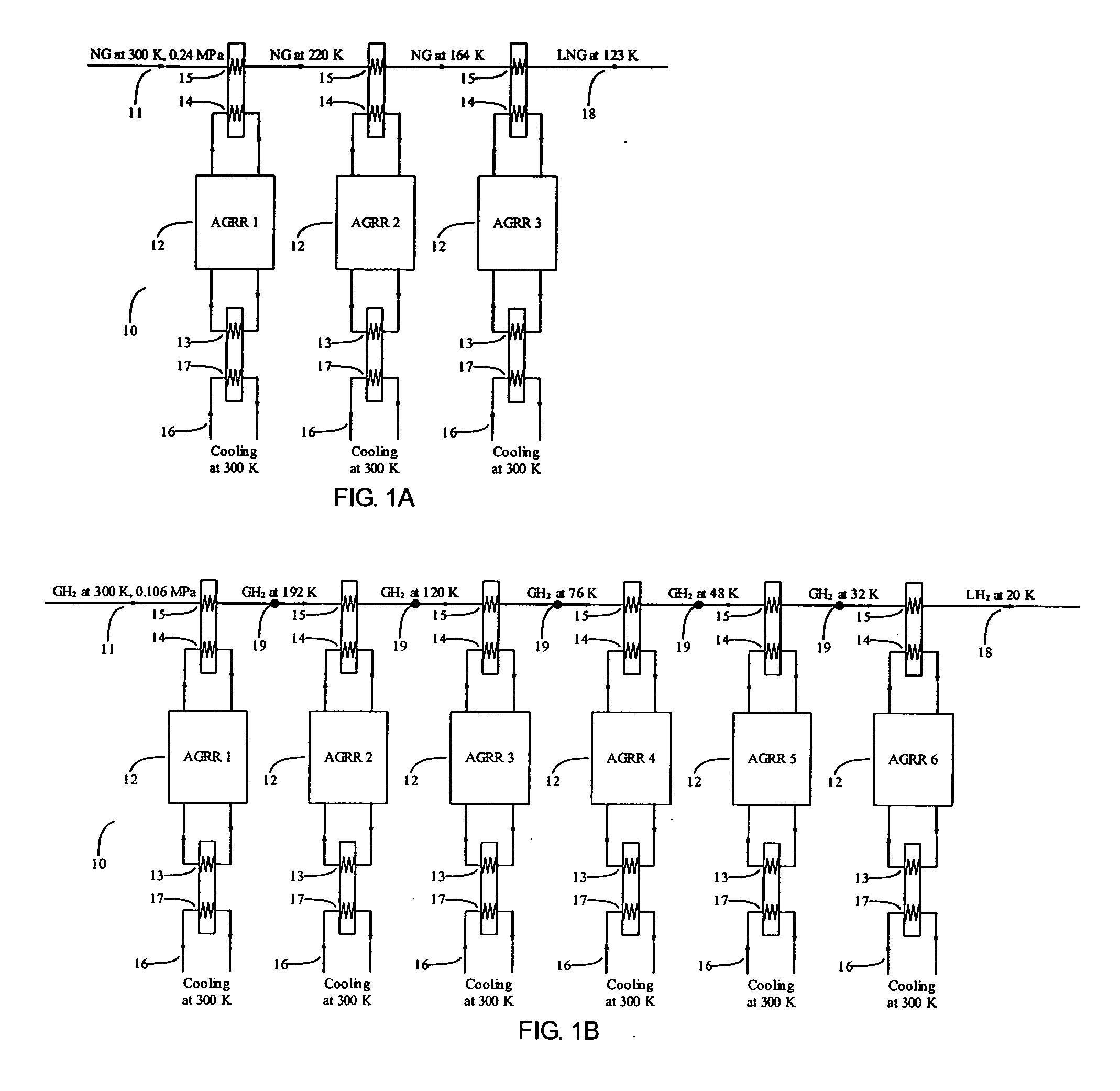
[0022]In a parallel-type AGRL each AGRR stage uses a refrigerant to pump a
thermal load from a cold temperature unique to each AGRR stage to a common
heat rejection temperature, e.g., near
room temperature. The final, or coldest, AGRR stage removes primarily
latent heat from a process stream to liquefy it and expels rejected heat at near room temperature. The previous successively warmer AGRR stages in a parallel-type AGRL remove primarily
sensible heat from the process stream to cool it and expel rejected heat at near room temperature. The efficiency of each AGRR stage depends on its inherent inefficiencies from real
heat transfer, fluid flow, refrigerant compression / expansion, and other processes necessary to pump heat from a colder to a warmer temperature. Since each AGRR stage spans a different temperature range in the disclosed AGRL, each stage can be optimally designed to achieve high efficiency by choices that minimize irreversible entropy creation in all aspects of the overall AGRL design. These include minimum temperature approaches in all heat exchangers, small pressure drops, and efficient work input and
recovery. By using a parallel-type AGRL configuration with highly efficient AGRR stages as disclosed a FOM of about 0.60 for
liquefaction of
hydrogen is achievable at relatively low cost. The combination of the several real AGRR stage efficiencies can provide natural gas or hydrogen liquefiers with FOMs of between 0.52 and 0.69. This performance is a
quantum increase over that of the best conventional liquefiers with FOMs of about 0.35. This AGRL invention provides a breakthrough in efficient and cost-effective hydrogen and natural gas
liquefaction.
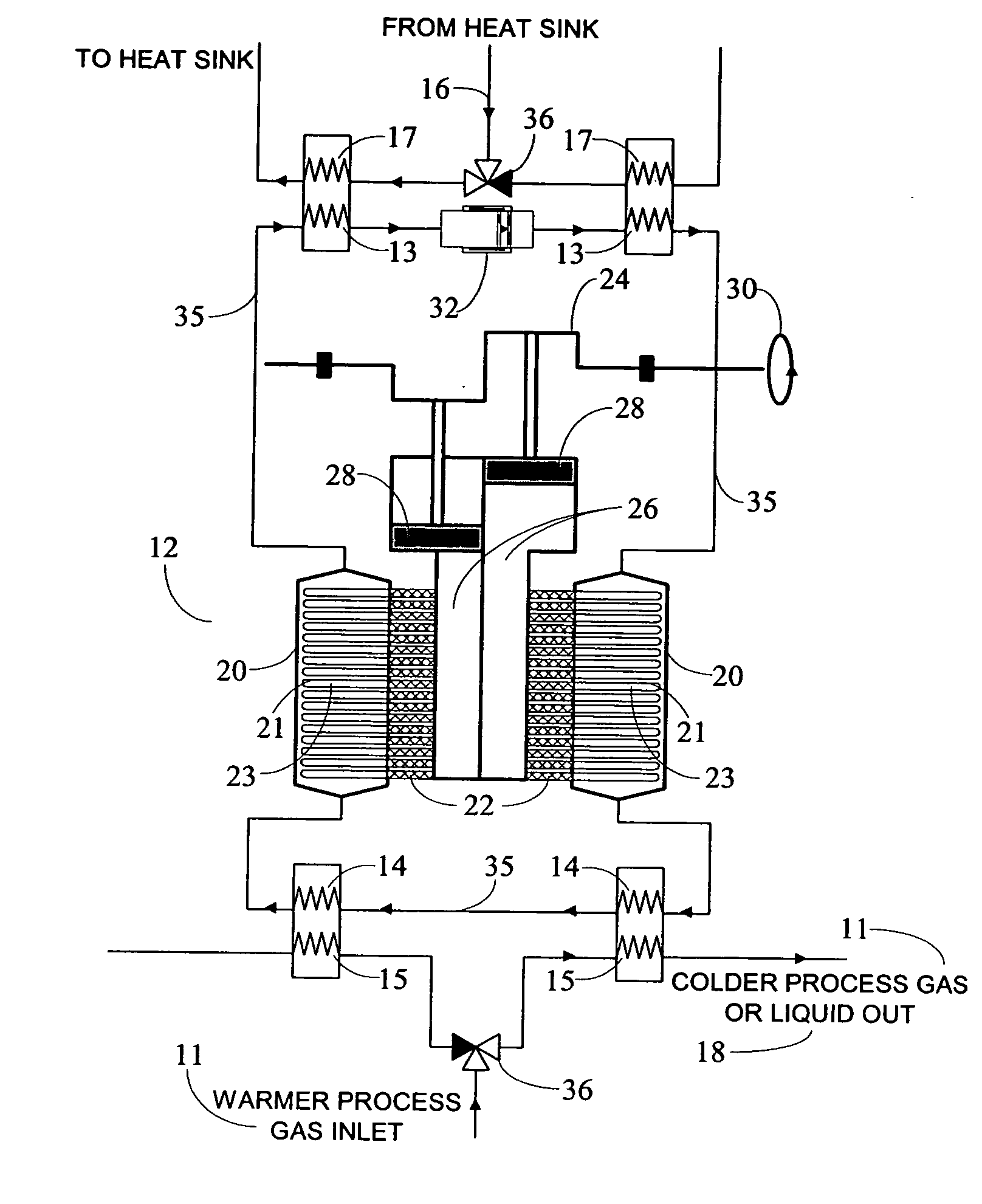
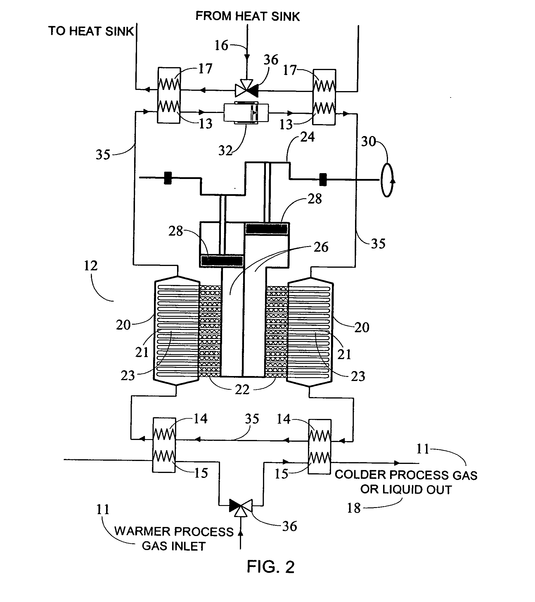
[0023]In another embodiment of the invention, the AGRL includes several stages of
refrigeration, with each stage including an array of discrete micro compressor-expander units (MCEU)5 configured as a high performance active regenerator having excellent
heat transfer, low pressure drop, and low longitudinal conduction with respect to the
heat transfer fluid and regenerator materials. The compressor-expander units are configured such that the compression of the refrigerant within a unit is coupled to the simultaneous expansion of the refrigerant within the other end of the unit, thereby allowing distributed work input and recovery from near ambient temperature to cryogenic temperatures necessary for liquefaction of natural gas or hydrogen. In this embodiment, the net work input is reduced substantially thus providing very efficient regenerative
refrigeration, no matter what the temperature span of the liquefier. This input of “distributed net work” is unique among gas liquefiers. 5 The MCEU or micro compressor expander unit may consist of a small
diameter tube, such as mm dimensions, with working refrigerant gas that is separately compressed at one end of the MCEU, and simultaneously separately expanded on the other end of the MCEU such that the work for compression of the refrigerant is partially compensated by work produced by the expansion.
[0024]Another feature of the AGRL is the use of multistage
refrigeration to a sequence of separate process stream heat exchangers containing the flowing process stream (natural gas or hydrogen gas) that approximates continuous cooling. In the case of hydrogen, associated ortho-to-para (o-p) exothermic
converters at each stage enables removal of the o-p heat as the hydrogen is cooled and liquefied. This multistage AGRR design feature markedly increases the
thermal efficiency of an AGRL compared to conventional hydrogen liquefiers, e.g. ones based on a Claude cycle.
[0025]In another embodiment of the disclosed invention, temperature approaches in between refrigerants in the individual tubes or MCEUs and heat exchange fluid in the active regenerators are kept small, thus avoiding the inherent inefficiency of conventional cycles when heat transfers across larger temperature spans. Thus, the temperature differences between the array of distributed MCEUs, between the
heat transfer fluid that couples the refrigerants in the MCEUs to the process stream heat exchangers and
heat sink exchangers of each AGRR, and between the heat exchange fluid and the process streams can be selected in a manner that optimizes efficient heat transfer and thereby increases thermodynamic efficiency.
[0026]The AGRL as disclosed and claimed is relatively simple in design as compared to other liquefiers, thus requiring fewer components, less expense, and simpler controls for automatic operation. These features are important attributes of commercial liquefiers.

