Cpp type giant magneto-resistance element and magnetic sensor

a technology of giant magnetoresistance and magnetic sensor, which is applied in the direction of magnetic bodies, instruments, transportation and packaging, etc., can solve the problems of affecting the magnetic recording density, and difficult to increase the mr ratio, etc., to achieve high mr ratio, low resistance, and high mr ratio

Inactive Publication Date: 2008-01-31
NAT INST OF ADVANCED IND SCI & TECH
View PDF2 Cites 76 Cited by
  • Summary
  • Abstract
  • Description
  • Claims
  • Application Information

AI Technical Summary

Benefits of technology

[0040]The CPP type GMR element having an ultrathin MgO barrier layer may obtain an MR element of a simple construction that has a low resistance and a high MR ratio without the need to use a comp

Problems solved by technology

In the above-described related art technique (1), there is no problem in the RA value, but it is difficult to increase the MR ratio.
Incidentally, in the above-described related art technique (2), a case where aluminum oxide is used as a barrier (an intermediate layer in an MR element) poses the problem that the M

Method used


Image

  • Cpp type giant magneto-resistance element and magnetic sensor
  • Cpp type giant magneto-resistance element and magnetic sensor
  • Cpp type giant magneto-resistance element and magnetic sensor

Examples


first exemplary embodiment

[0056]With reference to FIG. 6 to FIG. 12 and Table 1, the exemplary embodiments will be described. First, the present inventors' conception, experimental techniques and experimental results will be described. The inventors studied the spin filter effect by a single-crystal barrier, which is known in an MR element as a TMR element using an MgO barrier, and conceived causing the current confining effect to come into play by using an ultrathin single-crystal barrier, which is an MgO barrier whose thickness is reduced to a limit as the intermediate layer.

[0057]First, a description will be given of an increase in MR by the current confining effect. In a CPP-GMR element, a related art technique involves confining a current path by interposing an ultrathin oxide layer in an interface between an intermediate layer and a magnetization pinned layer (or a magnetization free layer), thereby to improve the MR ratio (refer to, for example, H. Fukuzawa et al., IEEE-Mag. Vol. 40 (2004), pp. 2236)....

second exemplary embodiment

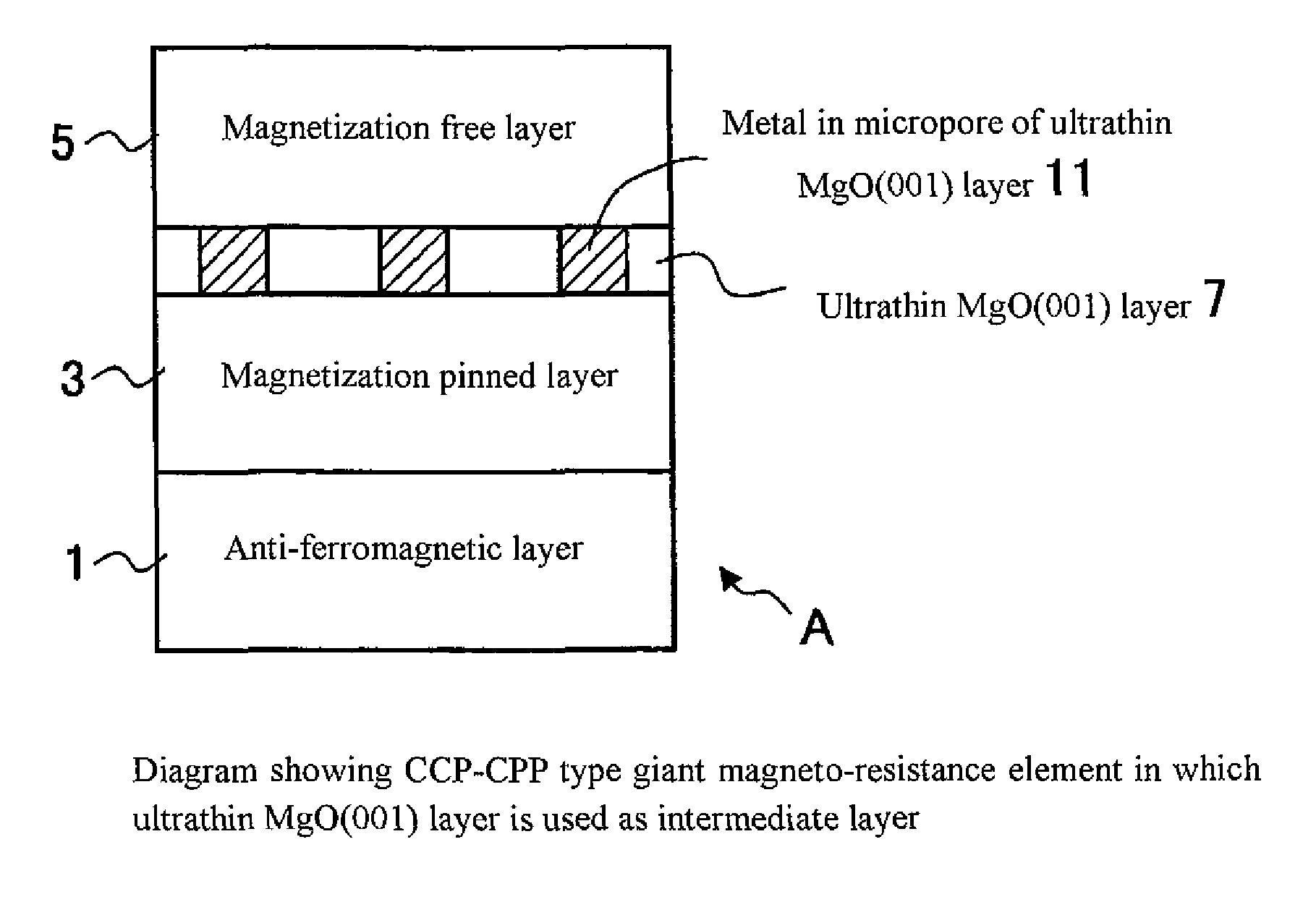
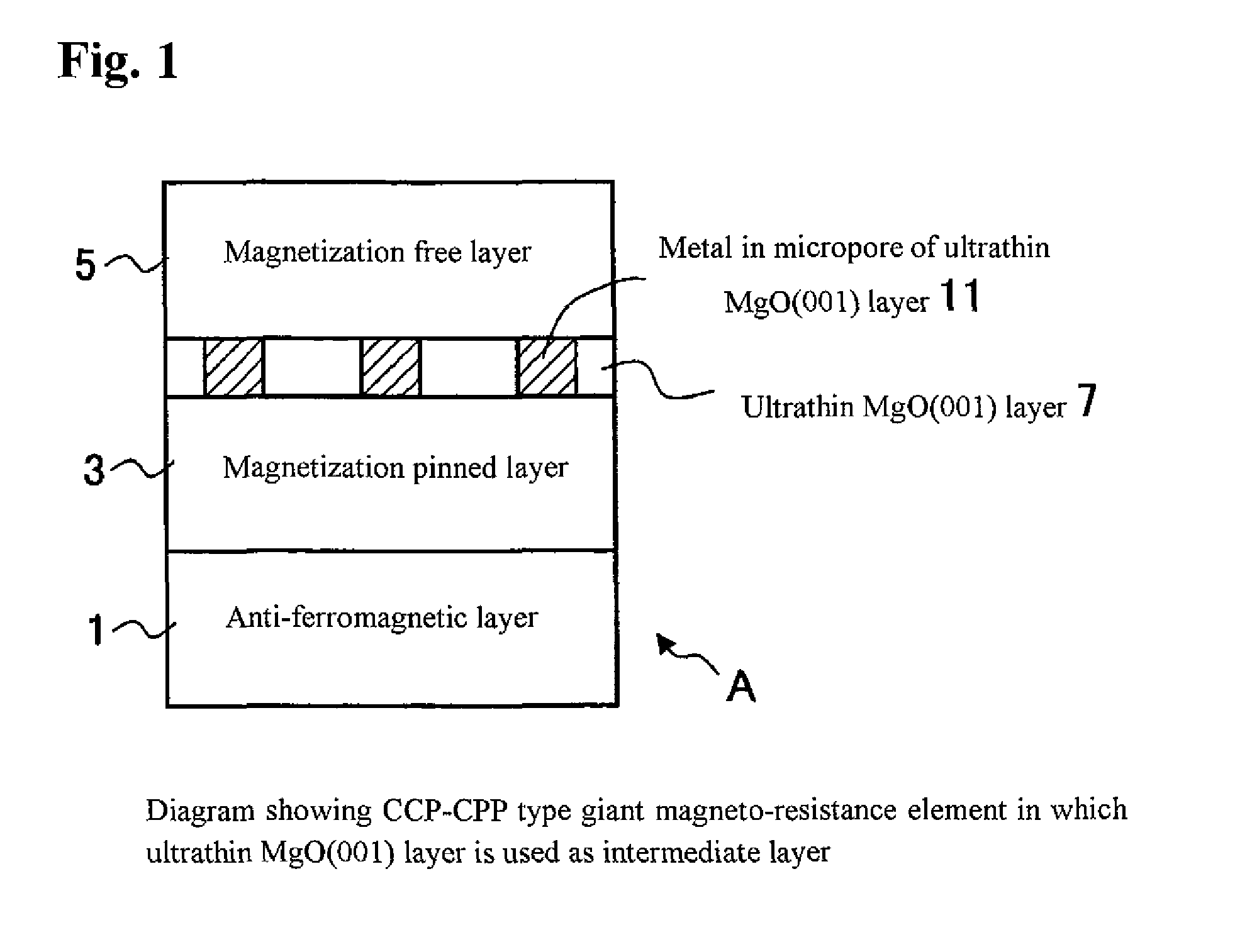
[0085]Next, the second exemplary embodiment will be described with reference to the drawings. FIG. 1 is a diagram that shows the construction of a CCP-CPP type MR element in the second exemplary embodiment. An MR element A has, as the intermediate layer, an ultrathin MgO(001) layer 7 having micropores with a thickness of not more than 1.0 nanometer. The MgO(001) layer used here refers to a magnesium oxide layer having a single-crystal structure whose crystal plane is oriented in the (001) direction (or a polycrystalline structure that is preferentially oriented in the (001) direction). When such a structure is used, the current confining effect is caused to come into play due to a metal 11 present in the micropores in the MgO(001) layer 7 and, therefore, the MR ratio increases. The structure of a spin valve type MR element in which an anti-ferromagnetic layer 1 is caused to be in close vicinity of a magnetization pinned layer 3 is adopted. However, it is not always necessary that th...

third exemplary embodiment

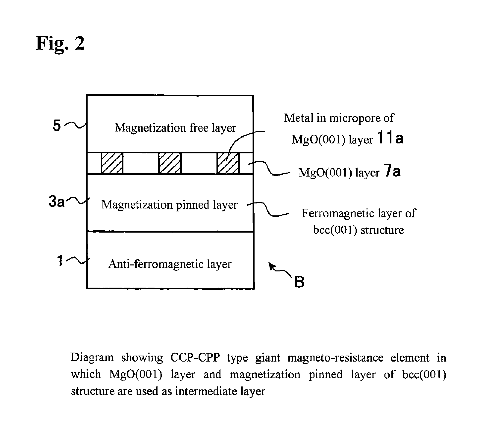
[0090]Next, the third exemplary embodiment will be described. FIG. 2 is a diagram that shows an example of the construction of a CCP-CPP type MR element in the third exemplary embodiment. This MR element in the third exemplary embodiment is such that in the MR element A of the second exemplary embodiment, a ferromagnetic material having a bcc (001) structure is used in a magnetization pinned layer 3a. Other features of the construction are the same as shown in FIG. 1. By adopting the above-described structure, the crystallizability and flatness of the MgO (001) layer are further improved and the MR resistance ratio increases further.


PUM


Abstract

Provided are a CCP (current confined path)-CPP (current-perpendicular-to-plane) type giant magneto-resistance (GMR) element having a giant magneto-resistance ratio in a low resistance region (a region of not more than 1 ohm per square micrometer) and a magnetic sensor using this GMR element. The CCP-CPP type GMR element A has a laminated structure of an anti-ferromagnetic layer, a magnetization pinned layer, an intermediate layer and a magnetization free layer, and is formed to have a construction in which a current flows perpendicularly to a film plane. By using an ultrathin magnesium oxide layer having micropores that is preferentially oriented in the (001) direction as the intermediate layer, the magneto-resistance ratio is enhanced, because a current flowing from the magnetization free layer to the magnetization pinned layer (or in the opposite direction) is confined by the metal in the micropores.

Description

BACKGROUND[0001]1. Technical Field[0002]Aspects of the present invention relate to a current perpendicular to plane (CPP) type giant magneto-resistance element having a construction in which a sense current flows in a direction perpendicular to the film plane, and a magnetic sensor having a CPP type giant magneto-resistance element.[0003]2. Related Art[0004]A magneto-resistance element is an electronic element that includes a magnetization pinned layer, an intermediate layer and a magnetization free layer and having a resistance value that varies depending on whether the directions of magnetization of the magnetization pinned layer and the magnetization free layer are parallel or antiparallel. In a related art magneto-resistance element, the thickness of each of the above-described three layers ranges from several tens of nanometers (nm) to several nanometers. Because electrons with upward spin and electrons with downward spin have different scatterings at an interface between the m...

Claims


Application Information

Patent Timeline
IPC IPC(8): G11B5/39
CPCB82Y25/00B82Y40/00G01R33/093G11B5/3906G11B5/398Y10T428/1107H01F41/307H01L43/08H01L43/12H01F41/325H01F10/3259G11B5/3983H10N50/01H10N50/10
Inventor YUASA, SHINJIFUKUSHIMA, AKIO
Owner NAT INST OF ADVANCED IND SCI & TECH
Why Eureka
Try Eureka