
Self-Sealing Ptfe Graft with Kink Resistance

a kink resistance, self-sealing technology, applied in the direction of prosthesis, coating, blood vessels, etc., can solve the problems of inability to safely withdraw blood for hemodialysis, inability to use a large artery for repeated punctures, and insufficient blood flow from the venous system to meet the required flow rate. , to achieve the effect of high porosity gra

Inactive Publication Date: 2008-01-31
CR BARD INC
View PDF99 Cites 76 Cited by
  • Summary
  • Abstract
  • Description
  • Claims
  • Application Information

AI Technical Summary

Benefits of technology

[0008] Accordingly, vascular grafts, and in particular ePTFE grafts and ePTFE AV grafts providing advantageous properties are described herein. In one aspect of the invention, a self-sealing vascular graft includes a generally tubular ePTFE substrate having a first surface and a second surface spaced from the first surface, wherein the ePTFE substrate is selected from the group consisting of a high porosity graft, a thin-wall graft and combinations thereof, and a layer of sealant disposed over one of the first and second surfaces of the substrate. In another aspect of the invention, a self-sealing graft includes a tubular ePTFE substrate, wherein the ePTFE substrate is either a high-porosity graft, a thin-wall graft or a combination thereof, and a layer of sealant disposed over at least a portion of the substrate. In yet another aspect of the invention, a graft for implantation as an AV fistula includes a tubular ePTFE substrate and a layer of sealant disposed over at least a portion of the substrate, wherein the sealant layer has a plurality of grooved sections spaced apart along the length thereof.

Problems solved by technology

Blood flow from the venous system is believed to be inadequate to meet the required flow rate and repeated punctures of large arteries are not feasible.
However, one potential drawback in using ePTFE AV grafts is that they cannot be used safely to withdraw blood for hemodialysis until about 14 days post-implant.
However, such sealing requires a combination of pressure and hemostasis, which does not lend to uniformity due to the many variables present during such procedures (dialysis technician / nurse skill level, operating conditions, etc.).
The ability to feel the pulse through the graft is generally defined as “palpability.” Most commercial ePTFE vascular grafts provide good palpability; however, when a layer of elastomeric sealant is placed on the surface of an ePTFE substrate, the palpability of the graft may be compromised if the layer is too thick.
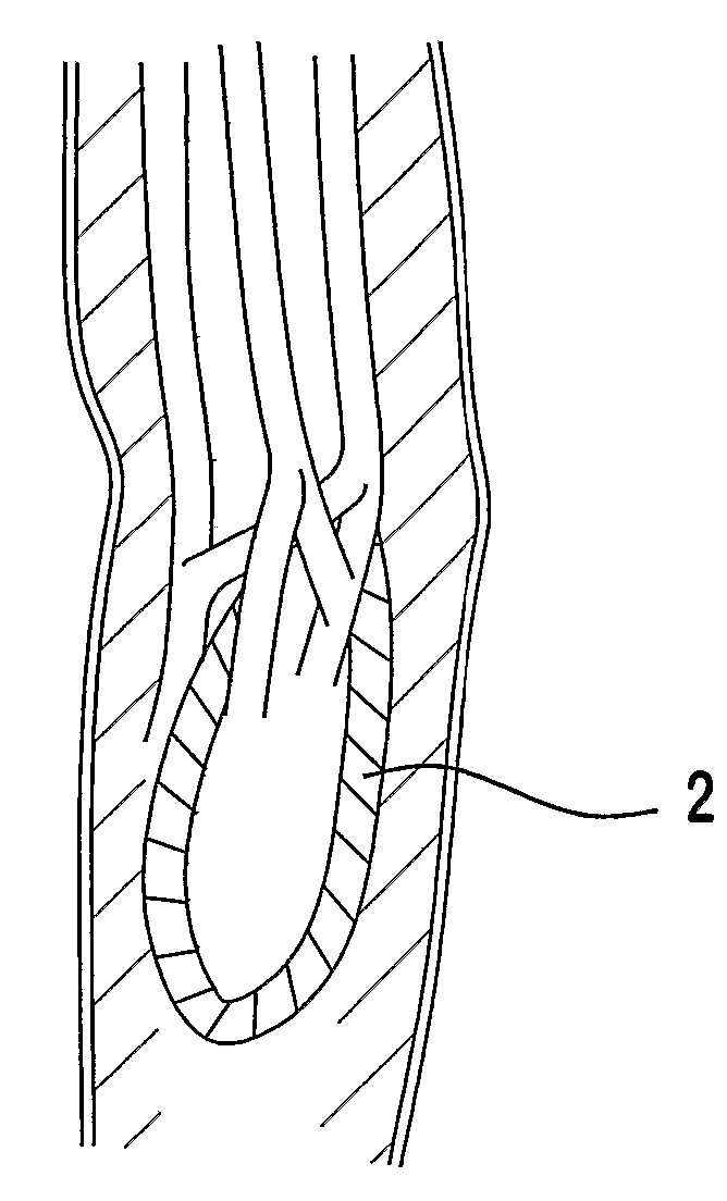
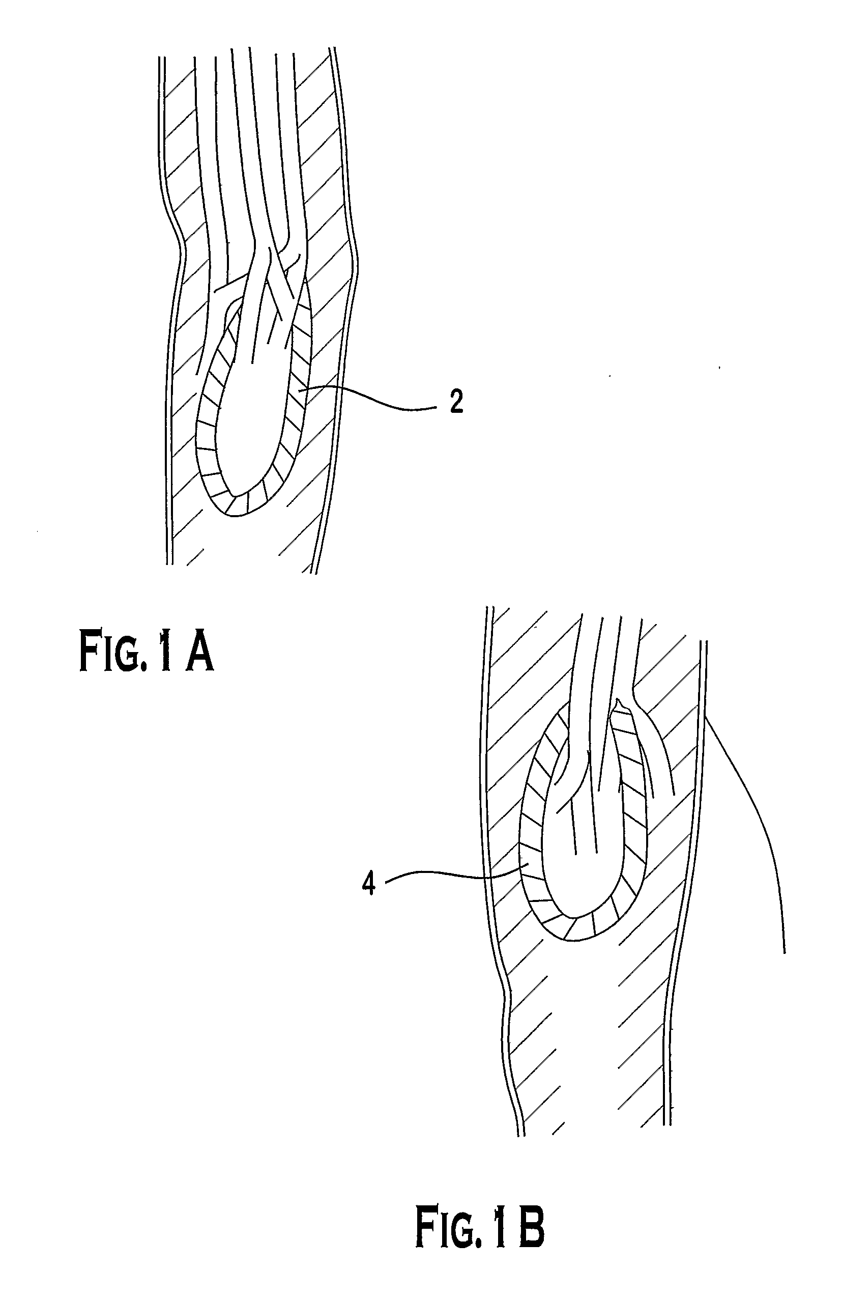
Another potential drawback in using ePTFE AV grafts for hemodialysis is that when implanted, there may be a tendency for the graft to form a kink at the loop site.
Clearly, such intervention is strongly disfavored as the likelihood of adverse outcomes are increased.
Unfortunately, it has been discovered that ePTFE grafts coated with elastomeric sealant or otherwise formed to address the problem of sealing can easily form kinks, presumably due to the stiffness of the graft at the loop region.
One other potential drawback in utilizing ePTFE material is that it is radially non-compliant compared to a native blood vessel, meaning that the wave propagation of blood, which causes a native blood vessel to expand and contract as pulses of blood flow therethrough, dissipates as it travels through a ePTFE graft.
This dissipation of the pulse can lead to various complications, such as compliance mismatch with respect to the host vessel.
Unfortunately, to date, it is believed that a radially compliant ePTFE graft that mimics the compliance of a native blood vessel has not been successfully developed.

Method used


Image

  • Self-Sealing Ptfe Graft with Kink Resistance
  • Self-Sealing Ptfe Graft with Kink Resistance
  • Self-Sealing Ptfe Graft with Kink Resistance

Examples


experiment a

[0052] High porosity (HP) grafts were provided, along with regular wall (RW) grafts and thin-wall (TW) grafts, each having a length of 6 cm and a diameter of 6 mm. A 25% solution of BioSpan® segmented polyurethane (commercially available from Polymer Technology Group, Inc.) in dimethyl acetamide (DMAC) was diluted to 9-12% solution using DMAC. The diluted solution containing polyurethane (PU) was spray-coated on selected grafts (i.e., RWPU, TWPU and HPPU (see table 3)). The solvent was removed by heating the coated grafts at an oven air temperature of 70° C. for about 10 minutes. Additional coats were applied to achieve the final coating thickness. The coated grafts were then dried in a substantial vacuum at a temperature of 70° C. for about 10-16 hours. Control RW, TW and HP grafts without coating were also provided.

TABLE 3CoatingThicknessPolymer CodeGraft Description(microns)Control RWRegular wall (RW) graft,N / A700 microns thick, 10-20 microns IND.Control TWThin wall (TW) graft,...

experiment b

[0064] A 6 mm ePTFE graft was provided. Approximately 12 grams Carbothane® PC-3585A was dissolved in approximately 88 grams dimethyl acetamide (DMAC) to prepare an approximately 12% solution. The polymer solution was then spray-coated using a Binks Model 2001 spray gun with a nozzle orifice diameter less than about 1 mm on the outside surface of the graft after the graft was first longitudinally compressed. The solvent was removed by heating the coated graft at an oven air temperature of about 70° C. for about 10 minutes. Additional coats were applied to achieve a coating having a thickness of about 50-300 microns. The coated graft was dried in a substantial vacuum at about 70° C. for about 1-16 hours. The exterior sealant surface of the coated graft was then sprayed with DMAC (for polyurethane sealant) to soften the polymer coat. It is noted here that in the case that a silicone based sealant is used for the outer sealant layer, a material such as P-Xylene can be used to soften the...

experiment c

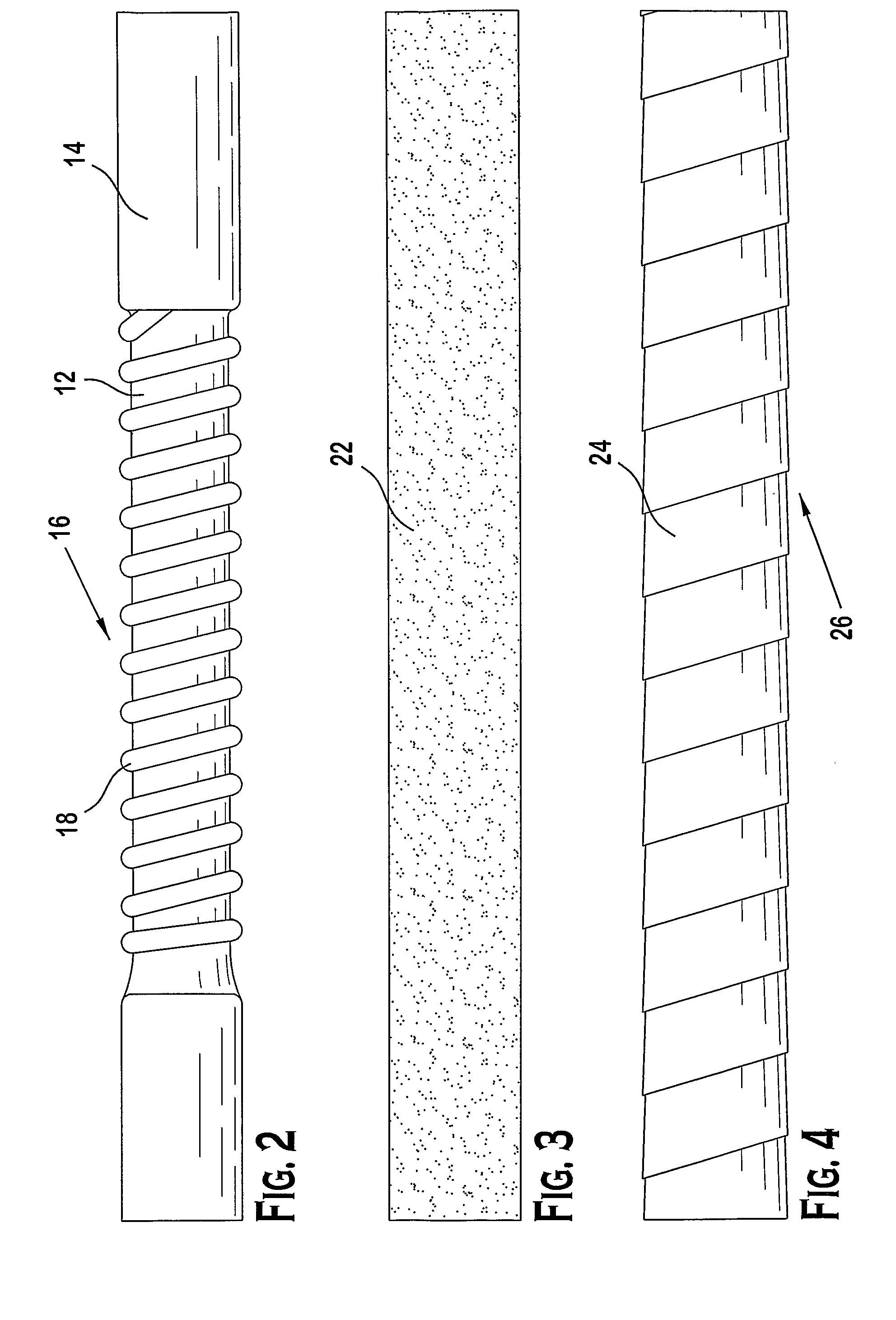
[0069] A polymer coated ePTFE graft was placed on a mandrel and was fixed between two chucks located on an automated rotary fixture. A graphic was designed using software that interfaces with a CO2 laser and scans the laser beam to etch the graphic on a given surface. Laser parameters were set and upon actuation of the start sequence, the laser cut grooves into the sealant layer of the coated ePTFE graft. The laser beam was adjusted so that only grooves in the sealant layer were created such that the ePTFE surface was not affected by the laser. Several types of grooves were cut and evaluated for kink resistance. The results of this experiment appeared to be that the best kink resistance resulted when the distance between grooves was minimized (i.e., in the range of about 1 mm to about 5 mm) and / or the angle of the grooves through the surface of the sealant layer was in the range of approximately 80-90° relative to the axis of the graft (i.e., approximately perpendicular with respect...


PUM

PropertyMeasurementUnit
distanceaaaaaaaaaa
thicknessaaaaaaaaaa
lengthaaaaaaaaaa

Abstract

A self-sealing vascular graft, including a substrate with a sealant layer and several optional additional layers, is described. The substrate can be ePTFE and the material used for the sealant and additional layers can be polyurethane. The sealant layer and additional layers may include one or more base layers, one or more foam layers, beading of different sizes and shapes, and ePTFE tape. A flared cuff may be integral to one or both ends of the substrate or may be attached to one or both ends. Various methods of making a self-sealing vascular graft are also described, including methods of disposition, methods of forming, methods of bonding and methods of attaching.

Description

PRIORITY [0001] This application claims the benefit of priority to U.S. Provisional Application No. 60 / 605,770, filed Aug. 31, 2004 and U.S. Provisional Application No. 60 / 692,172, filed Jun. 17, 2005, each of which is incorporated by reference into this application as if fully set forth herein.BACKGROUND OF THE INVENTION [0002] Patients suffering from reduced renal function or renal failure often have to undergo hemodialysis treatments. During dialysis, blood is withdrawn from the patient and is circulated through a hemodialysis machine. The machine removes toxic waste products and returns the purified blood to the patient. Typically, dialysis treatments are performed three times a week for the duration of a patient's life unless a kidney transplant procedure occurs. To successfully undergo hemodialysis treatment, blood must be circulated through the hemodialysis machine at 150 to 600 ml / minute or higher flow rate for about 3-4 hours. Blood flow from the venous system is believed t...

Claims


Application Information

Patent Timeline
Patent Type & Authority Applications(United States)
IPC IPC(8): A61F2/06
CPCA61L27/16A61L27/507A61L27/56A61F2/07A61L2420/08A61L2300/442A61L2300/44A61L27/34C08L27/18C08L75/04A61F2002/072A61F2/06A61F2250/0069A61M1/3655A61F2/94
Inventor EDWIN, TARUN J.ABBOTT, JAMIECOLE, HEIDI R.PATHAK, CHANDRASHEKHAR P.BOGERT, DAVID L.ELTON, RICHARDBROWN, FITZROYSHAHRIARI, KERESHMEH
Owner CR BARD INC
Learn More