
Controlling the synthesis gas composition of a steam methane reformer

a technology of steam methane reformer and synthesis gas composition, which is applied in the direction of combustible gas production, combustible gas purification/modification, waste based fuel, etc., can solve the problems of reducing the catalyst efficiency, serious environmental pollution, and a major dependence on petroleum, so as to improve the effect of economics

Inactive Publication Date: 2008-02-07
RGT UNIV OF CALIFORNIA
View PDF0 Cites 45 Cited by
  • Summary
  • Abstract
  • Description
  • Claims
  • Application Information

AI Technical Summary

Benefits of technology

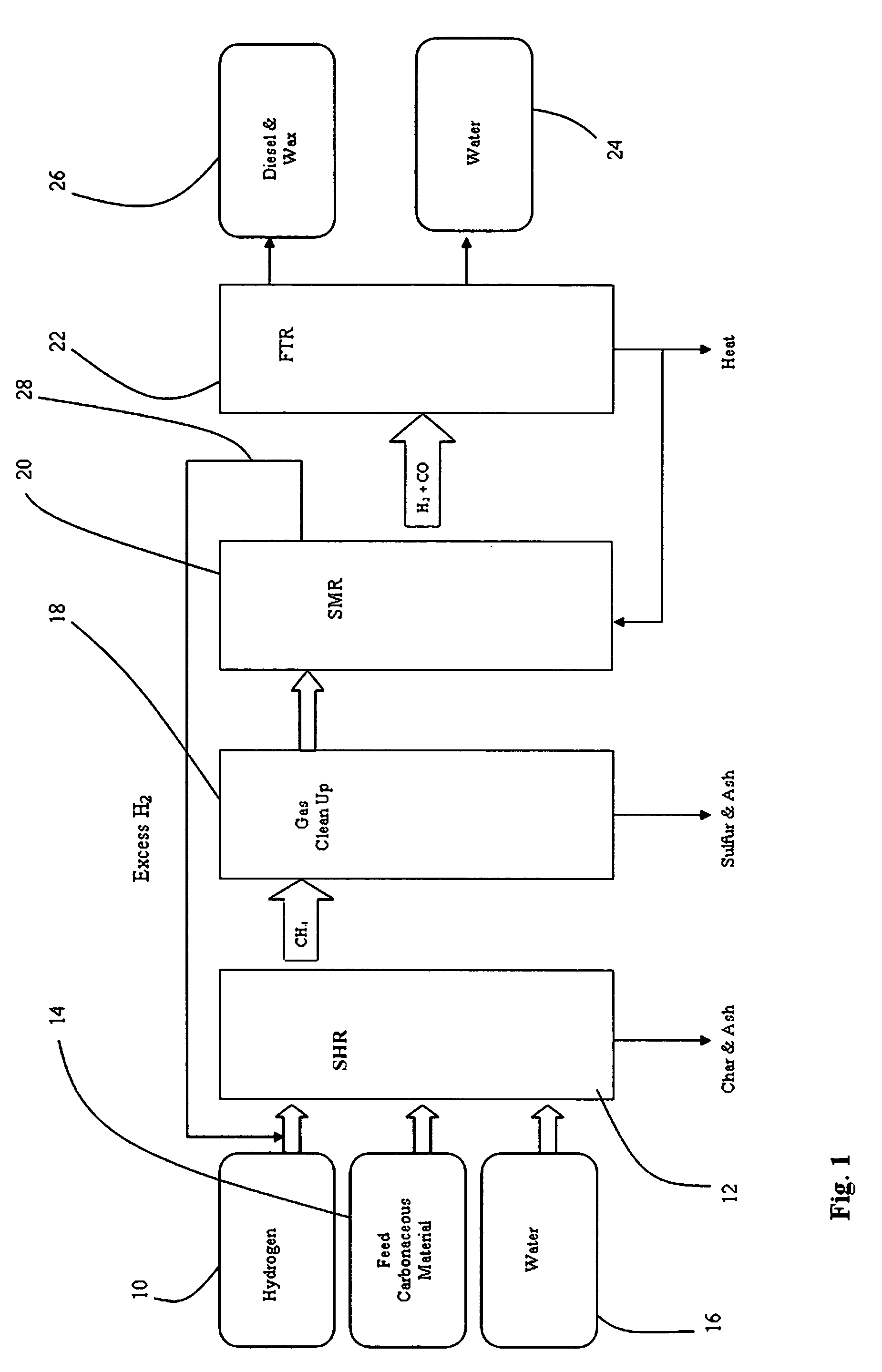
[0016]This invention provides an improved, economical method to control the synthesis gas composition obtained from a steam methane reformer that obtains its feedstock as product gas directly from a steam hydro-gasification reactor. The method allows control of the H2 / CO ratio by adjusting the hydrogen feed and the water content of feedstock into the SHR that supplies the SMR.
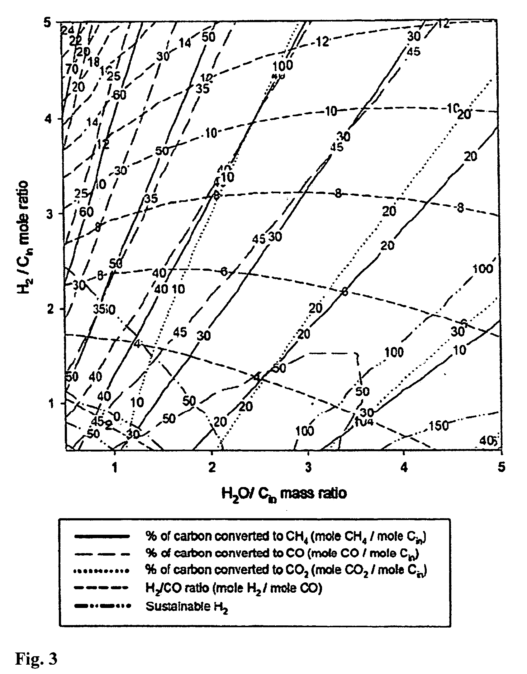
[0018]The mass percentages of the product stream at each stage of the process are calculated using a modeling program, such as the ASPEN PLUS™ equilibrium process that can relate the synthesis gas ratio of hydrogen to carbon monoxide to conversion ratios of the carbon content of the carbonaceous material. In accordance with the invention, by varying the parameters of solid to water ratio and hydrogen to carbon ratio, a sensitivity analysis can be performed that enables one determine the optimum composition of the slurry feedstock to the SHR to obtain a desired syngas ratio output of the SMR. Thus, the ratio of hydrogen to slurry water is determined by analysis of the effect on the synthesis gas ratio of (a) the ratio of solid content of the carbonaceous material to the slurry water and (b) the ratio of the hydrogen to carbon content of the carbonaceous material. This enables one to adjust the hydrogen feed and the water content of feedstock into the SHR that supplies the SMR to provide the desired ratio of hydrogen to carbon monoxide in the synthesis gas output of the SMR.

Problems solved by technology

Since the resources for the production of petroleum-based fuels are being depleted, dependency on petroleum will become a major problem unless non-petroleum alternative fuels, in particular clean-burning synthetic diesel fuels, are developed.
Moreover, normal combustion of petroleum-based fuels in conventional engines can cause serious environmental pollution unless strict methods of exhaust emission control are used.
Such a process allows for the application of current state-of-art engine exhaust after-treatment methods for NOx reduction, removal of toxic particulates present in diesel engine exhaust, and the reduction of normal combustion product pollutants, currently accomplished by catalysts that are poisoned quickly by any sulfur present, as is the case in ordinary stocks of petroleum derived diesel fuel, reducing the catalyst efficiency.
These waste sources of carbonaceous material are not the only sources available.
Unfortunately, open burning of biomass waste to obtain energy and heat is not a clean and efficient method to utilize the calorific value.
A number of processes exist to convert biomass and other carbonaceous materials to clean-burning transportation fuels, but they tend to be too expensive to compete on the market with petroleum-based fuels, or they produce volatile fuels, such as methanol and ethanol that have vapor pressure values too high for use in high pollution areas, such as the Southern California air-basin, without legislative exemption from clean air regulations.

Method used


Image

  • Controlling the synthesis gas composition of a steam methane reformer
  • Controlling the synthesis gas composition of a steam methane reformer
  • Controlling the synthesis gas composition of a steam methane reformer

Examples


example

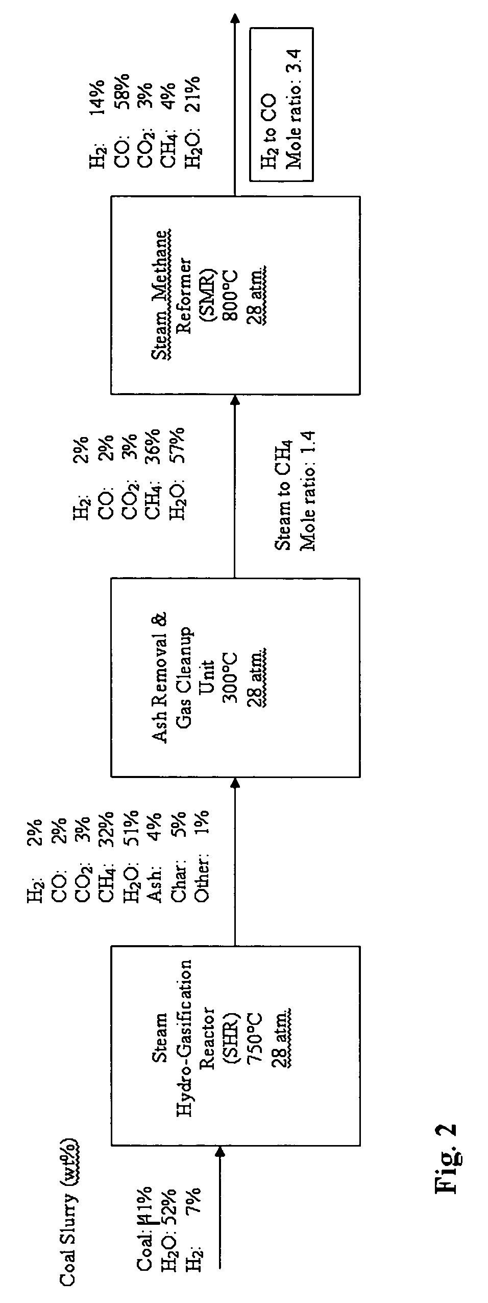
[0031]A mass balance process flow diagram is shown in FIG. 2. The mass percentages of the product stream at each stage of the process are provided in the figure. ASPEN PLUS™ equilibrium process modeling was used to calculate these values. ASPEN PLUS™ is a commercial computer modeling program that allows a process model to be created by specifying the chemical components and operating conditions. The program takes all of the specifications and simulates the model, executing all necessary calculations needed to solve the outcome of the system, hence predicting its behavior. When the calculations are complete, ASPEN PLUS™ lists the results, stream by stream and unit by unit, and can present the data in graphical form with determining ordinate and abscissa

[0032]As shown in FIG. 2, an SHR feedstock of hydrogen and 41% coal slurry results in the production of synthesis gas with a 3.4:l mole ratio of hydrogen to carbon monoxide in the SMR. The required feed hydrogen for the SHR can be supp...


PUM

PropertyMeasurementUnit
mole ratioaaaaaaaaaa
pressureaaaaaaaaaa
temperatureaaaaaaaaaa

Abstract

A method for controlling the synthesis gas composition obtained from a steam methane reformer (SMR) that obtains its feedstock as product gas directly from a steam hydro-gasification reactor SHR). The method allows control of the H2 / CO syngas ratio by adjusting the hydrogen feed and the water content of feedstock into a steam hydro-gasification reactor that supplies the SMR. The steam and methane rich product gas of the SHR is generated by means of hydro-gasification of a slurry of carbonaceous material and water. The mass percentages of the product stream at each stage of the process are calculated using a modeling program, such as the ASPEN PLUS™ equilibrium process. By varying the parameters of solid to water ratio and hydrogen to carbon ratio, a sensitivity analysis can be performed that enables one determine the optimum composition of the slurry feedstock to the SHR to obtain a desired syngas ratio output of the SMR. Thus one can adjust the hydrogen feed and the water content of feedstock into the SHR that supplies the SMR to determine the syngas ratio output of the SMR.

Description

FIELD OF THE INVENTION[0001]The field of the invention is the production of synthesis gas.BACKGROUND OF THE INVENTION[0002]There is a need to identify new sources of chemical energy and methods for its conversion into alternative transportation fuels, driven by many concerns including environmental, health, safety issues, and the inevitable future scarcity of petroleum-based fuel supplies. The number of internal combustion engine fueled vehicles worldwide continues to grow, particularly in the midrange of developing countries. The worldwide vehicle population outside the U.S., which mainly uses diesel fuel, is growing faster than inside the U.S. This situation may change as more fuel-efficient vehicles, using hybrid and / or diesel engine technologies, are introduced to reduce both fuel consumption and overall emissions. Since the resources for the production of petroleum-based fuels are being depleted, dependency on petroleum will become a major problem unless non-petroleum alternati...

Claims


Application Information

Patent Timeline
Patent Type & Authority Applications(United States)
IPC IPC(8): C01B3/24
CPCC01B3/38C10G2300/807C01B2203/04C01B2203/062C01B2203/0805C01B2203/1241C01B2203/1258C01B2203/127C01B2203/148C01B2203/84C10G2/30C10J3/00C10J2300/0916C10J2300/0946C10J2300/0966C10J2300/0973C10J2300/1659C10J2300/1807Y02E20/18Y02E50/32C10K1/024C10K1/143C10K1/16C10K1/165C10G2300/1003C10G2300/1011C10G2300/42C01B2203/0233Y02P20/145Y02P30/20Y02E50/30
Inventor NORBECK, JOSEPH M.PARK, CHAN SEUNG
Owner RGT UNIV OF CALIFORNIA
Learn More