
Shock timing technology

a cardioverter and timing technology, applied in the field of shock timing technology, can solve the problems of inability to determine the complete probability of success of the test at the time of the icd implant, the time required for the procedure is substantially shortened, and the contraction of the icd is too fast or too weak to pump blood effectively, etc., to achieve the effect of improving accuracy, speed and simplicity, and sufficient accuracy

Active Publication Date: 2008-02-07
IMPERCEPTION
View PDF32 Cites 52 Cited by
  • Summary
  • Abstract
  • Description
  • Claims
  • Application Information

AI Technical Summary

Benefits of technology

[0129] The principal advantage of the present invention is the capacity to automate determination of the optimal first shock strength for transvenous ICDs using only implanted electrodes by determining the ULV with improved accuracy, safety, speed and simplicity. The present invention is substantially improved over previous methods of determining the ULV for purposes of predicting the DFT and is of sufficient accuracy that conventional DFT testing is unnecessary. The time required for the procedure is substantially shortened by diminishing the number of episodes of fibrillation, the number of shocks in regular rhythm, the need to record a 12-lead surface ECG, and the need to make cumbersome measurements from the 12-lead surface ECG. The present invention is easy to apply because all measurements can be automated in the software of the ICD or programmer.
[0130] The timing systems, apparatus and method disclosed herein are useful with the devices and methods for determining defibrillation shock strength utilizing timed T-wave shocks in described above. In addition, they may be used with other devices and methods.
[0131] Digital signal processing techniques have been used in cardiac electrophysiology. For example, Köhler et al, used digital signal processing techniques for the purpose of improving the accuracy of automated detection of surface ECG signals.
[0132] The maximum of the first derivative of the T-wave is also an inflection point (TI), corresponding to the zero point of the second derivative as the first derivative changes from concave up to concave down. Depending on the method used for calculation, this zero point of the second derivative may, under some conditions, be less susceptible to noise than the first derivative.
[0133] Analysis of two or more simultaneously acquired biological signals to measure an important parameter is well-established approach. Multiple methods and techniques have been developed to combine signals for this purpose.
[0134] In cardiac electrophysiology, previous investigators have combined either information from multiple electrograms or information from different methods of signal processing applied to the same electrogram. For example electrogram voltage, its first derivative with respect to time, and its second derivative with respect to time have been combined to improve discrimination of local signals from far-field signals in a single electrogram. Combinations of signals have been used to improve other solutions in electrocardiography, such as diagnosis of acute myocardial infarction.

Problems solved by technology

It results in cardiac contractions that are too fast or too weak to pump blood effectively.
Because the devices must be small enough for convenient implantation, ICDs are limited in their ability to store electrical energy.
Thus the goal of testing at the time of ICD implant cannot be to determine a complete probability of success curve.
One significant disadvantage of all DFT methods is the necessity to repeatedly fibrillate and then defibrillate the patient's heart to determine the DFT.
A second disadvantage is that successful defibrillation is a probability function of shock energy, not an all or none phenomenon described by a simple threshold.
If fibrillation is not induced, a safe shock strength is predicted to be incrementally greater than tested shock strength by about 5 J. This safety-margin approach does not determine the minimum (optimal) safe shock strength, but rather only ensures that the programmed shock strength is sufficient.

Method used


Image

  • Shock timing technology
  • Shock timing technology
  • Shock timing technology

Examples


Embodiment Construction

1. Basic Devices and Methods for Determining Defibrillation Shock Strength Utilizing Timed T-wave Shocks

[0088] The Devices and Methods for Determining Defibrillation Shock Strength Utilizing Timed T-wave Shocks are particularly well suited for use with the Timing Systems, Devices and Method described in Section 2 below.

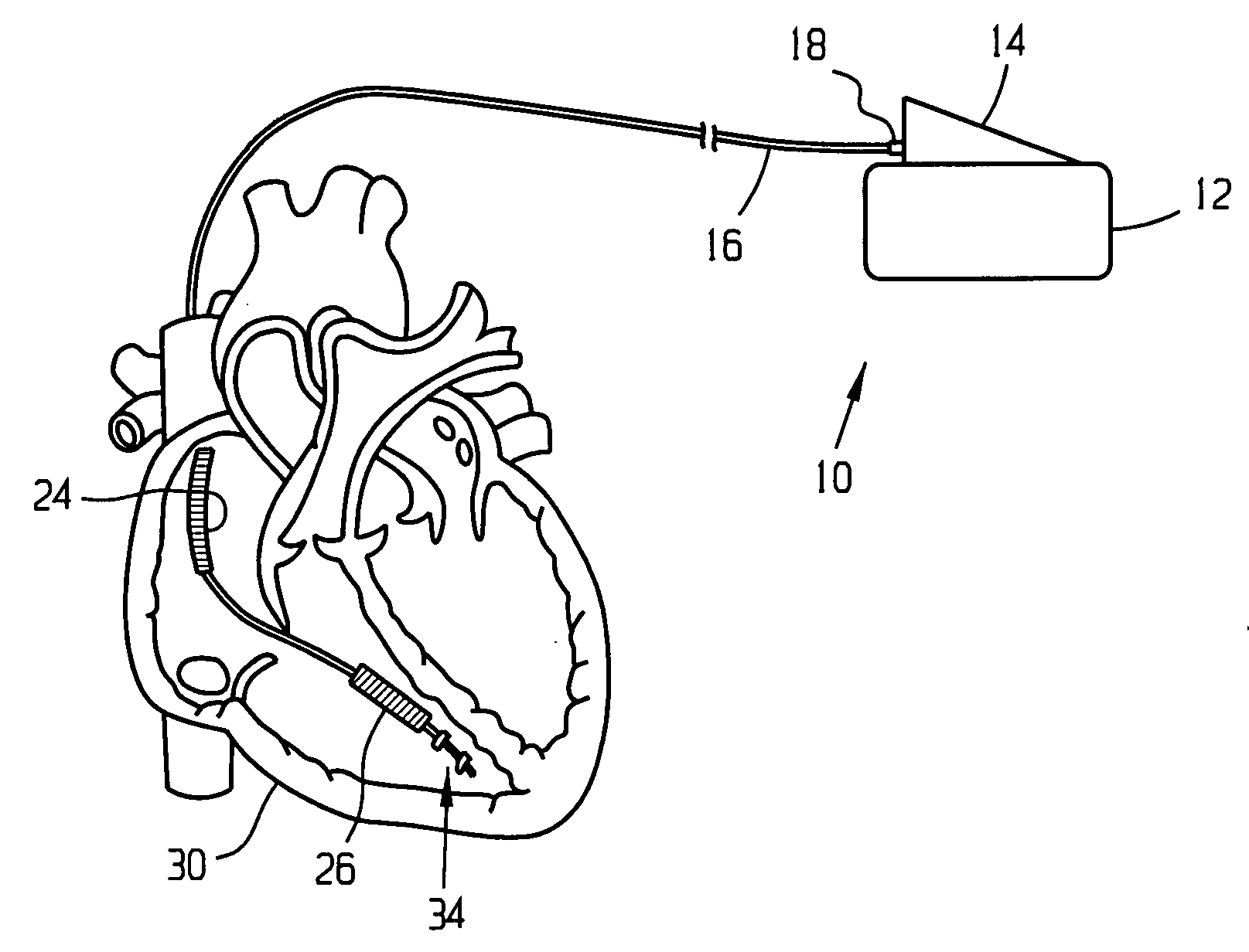
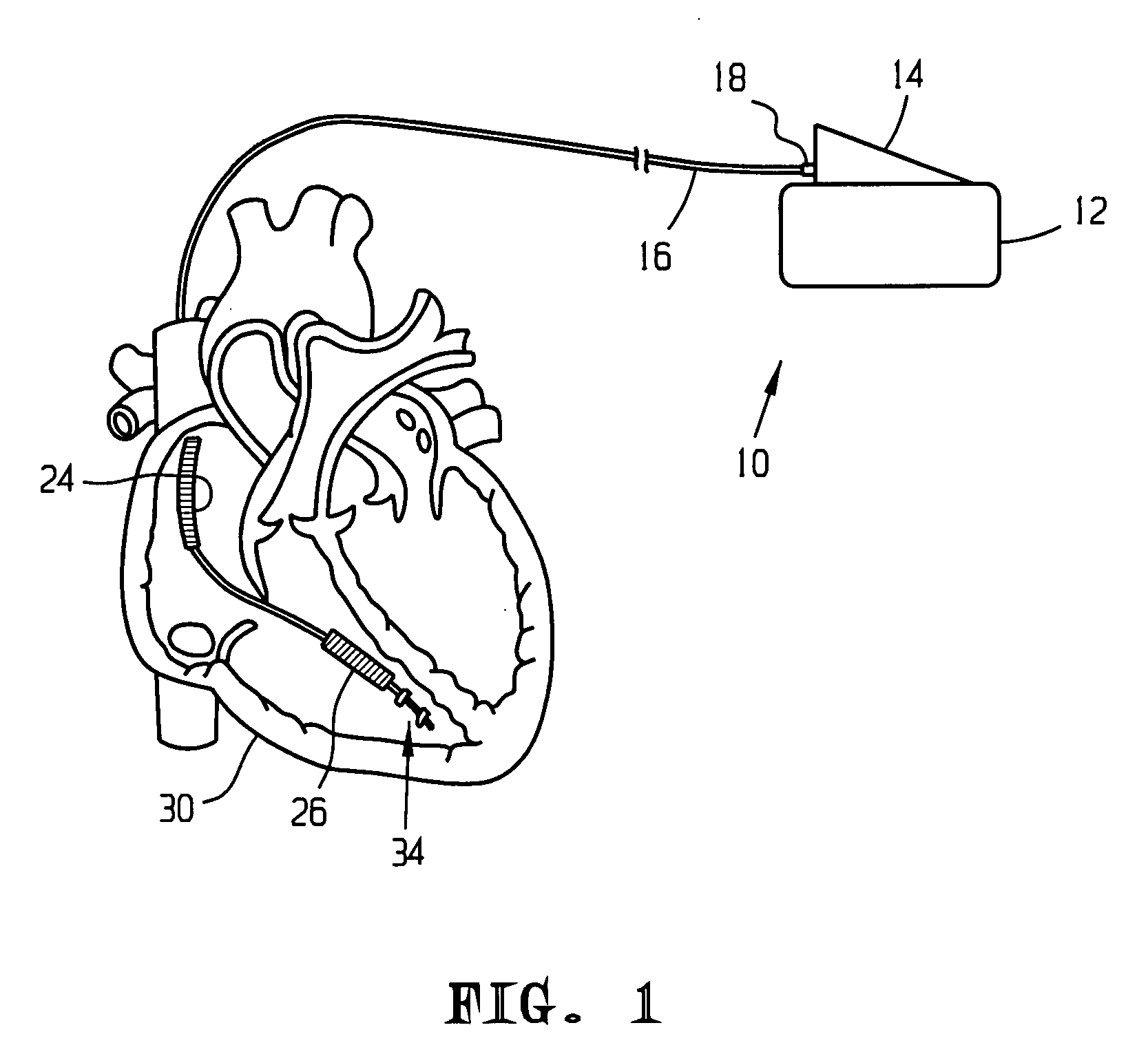
[0089] Referring to FIG. 1, an embodiment of the present invention is depicted as an ICD system 10 comprising an implantable electrical pulse generating housing or “can”12, an electrical connector pin housing 14, an implantable intravascular catheter 16 electrically connected to pin housing 14 via a pin connector 18. Catheter 16 carries proximal defibrillation discharge electrode 24 and distal defibrillation discharge electrode 26, electrodes 24 and 26 sometimes being referred to as “coils”, and is configured to position proximal electrode 24 within right atrium 28 and position distal electrode 26 within right ventricle 30. Catheter 16, also carries a set of pacing...


PUM


Abstract

A method for accurately determining timing points for T-wave shocks is particularly useful in a system for determining a cardiac shock strength in an implantable cardioverter defibrillator (ICD. The method involves acquiring at least one first signal, acquiring at least a second signal, comparing the signals, and selecting a timing point with the T-wave of the signal. The first and second signals may be two different aspects of a single electrogram, first and second electrograms, or a combination thereof. Comparison preferably involves signal alignment and qualitative analysis.

Description

CROSS-REFERENCE TO RELATED APPLICATIONS, IF ANY [0001] This application is a continuation-in-part of U.S. patent application Ser. No. 10 / 706,793 filed on Nov. 12, 2003, which claims the benefit under 35 U.S.C. §119(e) of co-pending U.S. Provisional Patent Application Ser. No. 60 / 372,402, filed Apr. 15, 2002, which is hereby incorporated by reference.STATEMENT REGARDING FEDERALLY SPONSORED RESEARCH OR DEVELOPMENT [0002] Not applicable. REFERENCE TO A MICROFICHE APPENDIX, IF ANY [0003] Not applicable. BACKGROUND OF THE INVENTION [0004] 1. Field of the Invention [0005] The present invention relates, generally, to implantable cardioverter defibrillators (ICDs) and defibrillation methods, and particularly to a method and apparatus for determining the optimal shock strength for defibrillation utilizing the upper limit of vulnerability (ULV). More particularly, the invention relates to methods of timing T-wave shocks for purposes of determining cardiac shock strength based on multiple sign...

Claims


Application Information

Patent Timeline
Patent Type & Authority Applications(United States)
IPC IPC(8): A61N1/00
CPCA61B5/0452A61B5/046A61B5/0472A61B5/7239A61N1/3943A61N1/3987A61B5/7257A61B5/366A61B5/361A61B5/349A61B5/355
Inventor SWERDLOW, CHARLES
Owner IMPERCEPTION
Learn More