
External electrode fluorescent lamp with optimized operating efficiency

a fluorescent lamp and fluorescent lamp technology, applied in the direction of electrical discharge lamps, basic electric elements, electrical apparatus, etc., can solve the problems of high voltage, high firing voltage of fluorescent lamps, safety risks, etc., and achieve the effect of low emission function and high secondary electron emission ra

Inactive Publication Date: 2008-02-14
SCHOTT AG
View PDF0 Cites 345 Cited by
  • Summary
  • Abstract
  • Description
  • Claims
  • Application Information

AI Technical Summary

Benefits of technology

[0009] Due to the fact that glasses represent insulators the probability for the emission of secondary ions is very low if an ion from the glass plasma is neutralized on the surface of the cathode. This results in a high firing voltage in fluorescent lamps. Based on the high firing voltage, high voltages must be used in the flat panel screen, which represents a safety risk. In addition, the efficiency diminishes since a lag time occurs during the half wave of the driving alternating voltage.
[0022] According to the present invention very specialized glasses and / or coatings for glasses are made available which contain at least one doping agent, especially preferably a combination of several doping agents. This makes it possible for the utilized encapsulating glass and / or the interior coating of the encapsulating glass to provide an optimum operating efficiency of the EEFL-type fluorescent lamp due to the low work function Wa for the electrons. In addition, this allows for the firing voltage of the EEFL-type fluorescent lamp to be lowered to a low level.
[0025] Beyond this there is the possibility, either alternatively or additionally to incorporate heavy metals into the glasses (group (b)). This concerns, for example, a composition, of oxides, especially lanthanum, bismuth, barium and / or lead. These are particularly easily polarizable ions whereby the cloud of electrons can be easily shifted toward the core.
[0029] It is especially desirable if the sum of the amount of dopant from group (a) and group (b) that are present in the encapsulating glass has a lower limit of ≧15 weight-%, preferably ≧20 weight-%, more especially preferably ≧30 weight-% and an upper limit of ≦80 weight-%, preferably ≦75 weight-%, more especially preferably ≦70 weight-%. In the same manner it is especially desirable if the sum of the amount of dopant from group (a) and group (b) in the partial interior coating has a lower limit of ≧15 weight-%, preferably ≧20 weight-%, more especially preferably ≧30 weight-% and an upper limit of ≦80 weight-%, preferably ≦75 weight-%, more especially preferably ≦70 weight-%. This particularly facilitates attainment of the advantageous characteristics of the present invention.
[0032] The doping agents utilized in accordance with the present invention lead to a clear lowering of the work function Wa for the electrons in the glass composition and / or the coating of the encapsulating glass, to a value of <6 eV, preferably <5 eV, more preferably 0 eV<Wa<5 eV, especially preferably 0 eV<Wa<4 eV, more especially preferably 0 eV<Wa<3 eV. In dependence on the work function Wa the so-called secondary emission rate y can continue to be regulated. Accordingly, the encapsulating glasses and / or the interior coating of the encapsulating glasses include a composition having a high secondary electron emission rate y, causes, for example, Hg—, Xe—, Ne— and / or Ar-ions when being bombarded thereby. The secondary electron emission rate y is regulated, preferably by way of selecting the doping agents in suitable amounts, so that: y>0.01, especially preferred y>0.05, more especially preferred y>0.1 applies. By regulating the secondary electron emission rate y, the encapsulating glasses or their interior coatings for these encapsulating glasses for the application in EEFL-type fluorescent lamps can successfully be further optimized, so that the desired low emission function Wa for the electrons is maintained. For example, this can be achieved by different combinations of the doping agents listed above, and by modifying the amounts used.

Problems solved by technology

This results in a high firing voltage in fluorescent lamps.
Based on the high firing voltage, high voltages must be used in the flat panel screen, which represents a safety risk.
In addition, the efficiency diminishes since a lag time occurs during the half wave of the driving alternating voltage.

Method used


Image

  • External electrode fluorescent lamp with optimized operating efficiency
  • External electrode fluorescent lamp with optimized operating efficiency
  • External electrode fluorescent lamp with optimized operating efficiency

Examples


Embodiment Construction

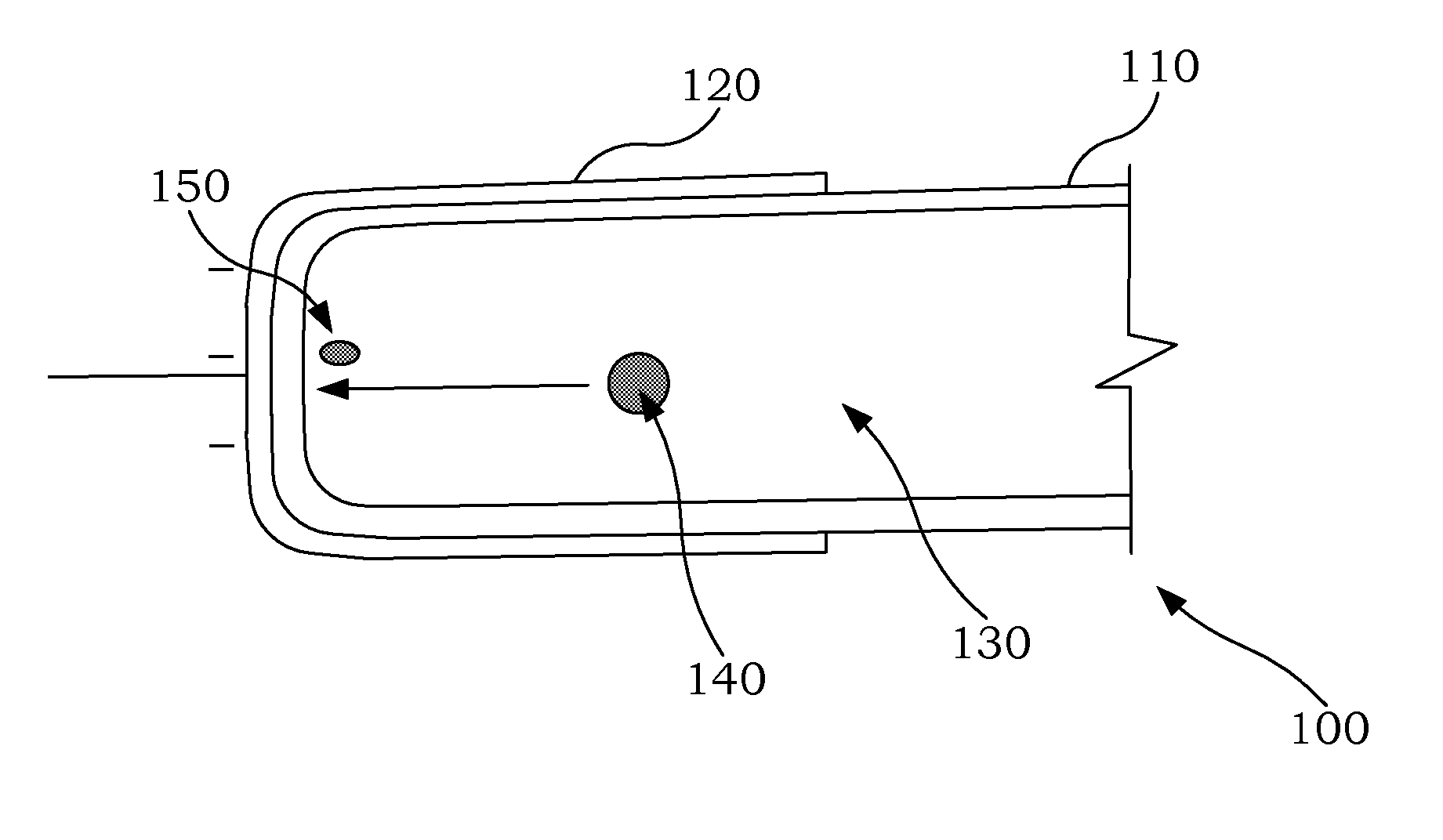
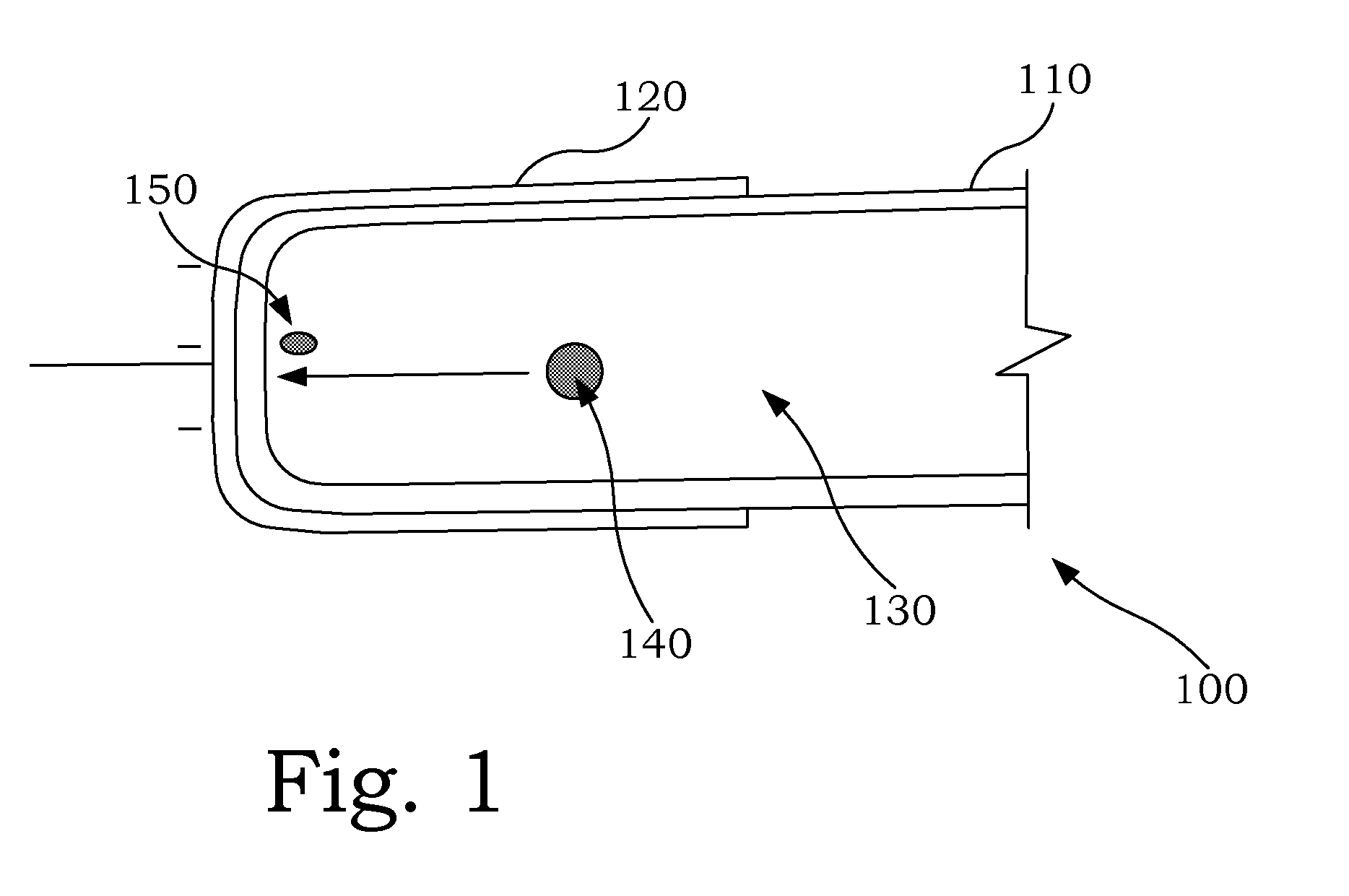
[0046] Referring now to FIG. 1, there is illustrated a fluorescent lamp of the present invention, especially a miniaturized fluorescent lamp 100, which is constructed from an encapsulating glass 110, a metal contact 120 which is, for example, provided in the form of an exterior metal cap, as well as a discharge gas 130 which is located inside EEFL-type fluorescent lamp 100. The gas mixture is utilized as a discharge gas 130. Consequently a capacitor is practically created in the interior of the encapsulating glass through which the electrical power is provided as alternating voltage. Encapsulating glass 110 serves not only as a dielectric in this capacitor, but its interior surface also assumes the additional function as a cathode material. An ion 140 from discharge gas 130 migrates to the interior surface of encapsulating glass 110, which functions as a cathode material, where it is neutralized. In accordance with the present invention, encapsulating glass 110 possesses at least on...


PUM

PropertyMeasurementUnit
Thicknessaaaaaaaaaa
Thicknessaaaaaaaaaa
Percent by volumeaaaaaaaaaa

Abstract

An EEFL-type fluorescent lamp for backlighting of displays or screens, whereby the encapsulating glass and / or a (partial) coating of the interior surface of the encapsulating glass are provided which possess a low work function Wa for the electrons of <6 eV, preferably <5 eV, more preferably 0 eV<Wa<5 eV, especially preferably 0 eV<Wa<4 eV, more especially preferably 0 eV<Wa<3 eV. This allows for the operating efficiency to be optimized and the firing voltage to be lowered.

Description

BACKGROUND OF THE INVENTION [0001] 1. Field of the Invention [0002] The invention relates to an External Electrode Fluorescent Lamp (EEFL)-type fluorescent lamp with optimized operating efficiency. [0003] 2. Description of the Related Art [0004] It is known that fluorescent lamps, generally includes thin-walled glass tubes that may be utilized for backlighting of Thin Film Transistor (TFT) flat screens. In a newer development, lamps to which electrical power is provided by way of alternating voltage are available for this application. These are the so-called EEFLs (External Electrode Fluorescent Lamps). In this type of lamp no metal electrodes extend through the glass. The glass serves as the dielectric which, for instance, is equipped with an outer metal cap, with an ionized gas such as mercury or an inert gas in the interior of the tube, thereby creating a capacitor through which electrical power in the form of alternating voltage can be provided. The glass serves not only as a di...

Claims


Application Information

Patent Timeline
IPC IPC(8): H01J65/04
CPCC03C3/068C03C3/07C03C3/095H01J65/046C03C4/12H01J61/302C03C3/102C03C3/12H01J9/24H01J61/30H01J65/00
Inventor LETZ, MARTINFECHNER, JORG H.HUEBER, BRIGITTEOTT, FRANZ
Owner SCHOTT AG
Learn More