Projection objective and projection exposure apparatus including the same

a technology which is applied in the field of projection objective and projection exposure apparatus including the same, and can solve the problems of high price of available materials, difficult color correction, and no useful image obtained outside the effective image field

Inactive Publication Date: 2008-02-14
CARL ZEISS SMT GMBH
View PDF29 Cites 31 Cited by
  • Summary
  • Abstract
  • Description
  • Claims
  • Application Information

AI Technical Summary

Benefits of technology

[0022] It is an object of the invention to provide a reduction projection objective adapted to dry lith...

Problems solved by technology

Outside the effective image field the correction status of imaging aberrations and/or the brightness may deteriorate such that no useful image is obtained outside the effective image field.
Since there are only few materials sufficiently transparent in that wavelength region (e.g. synthetic quartz glass (fused silica) and crystalline fluorides, such as calcium fluoride) and the Abbe numbers of those materials are close together, the correction for chromatic aberrations (color-correction) becomes difficult.
The high prices of the...

Method used


Image

  • Projection objective and projection exposure apparatus including the same
  • Projection objective and projection exposure apparatus including the same
  • Projection objective and projection exposure apparatus including the same

Examples


second embodiment

[0072]FIG. 3 shows projection objective 300 designed as a dry objective for operating wavelength λ=248 nm, having NA=0.88 and image field size 26 mm*5.5 mm. The specification is given in tables 3, 3A.

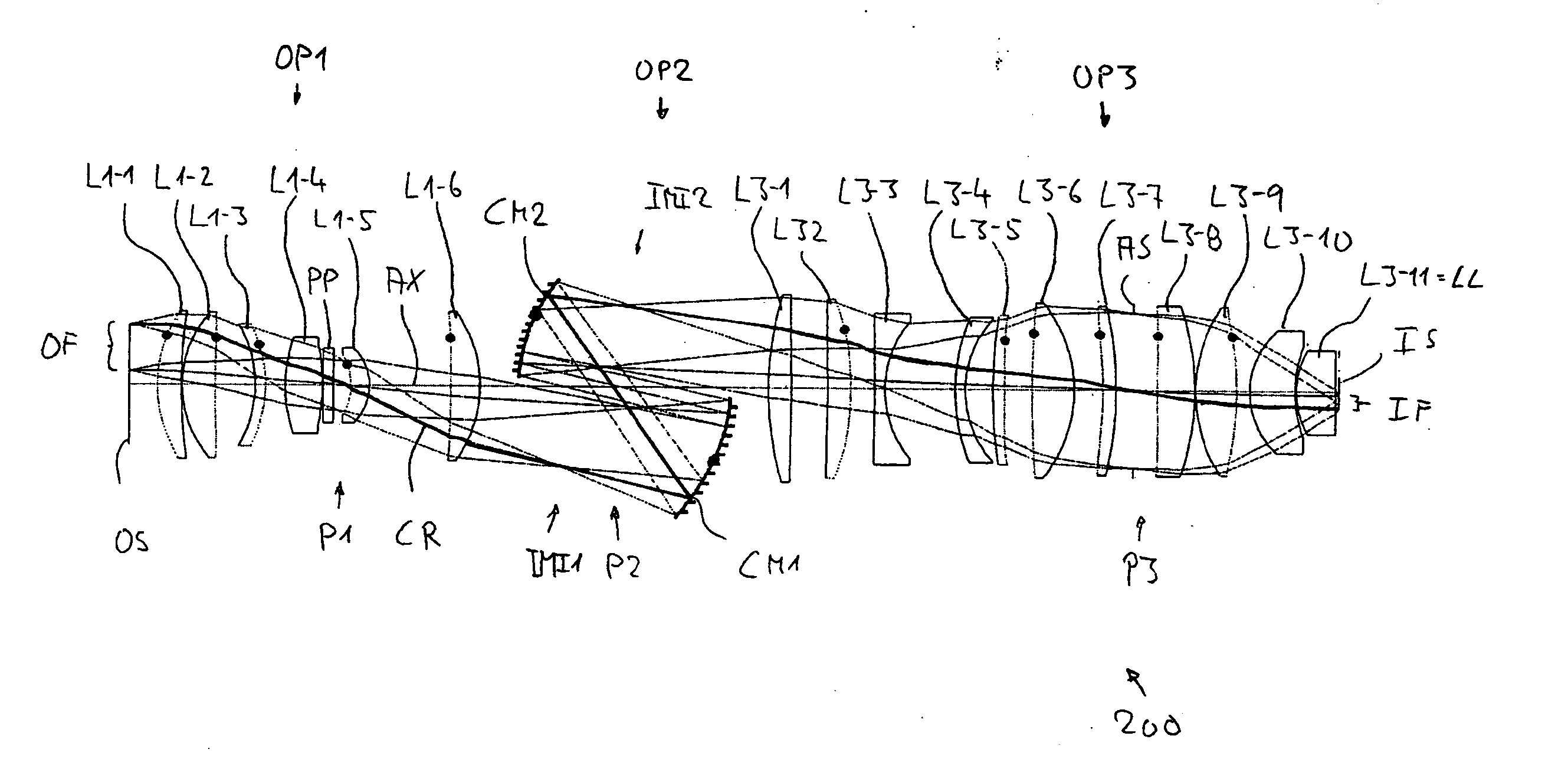
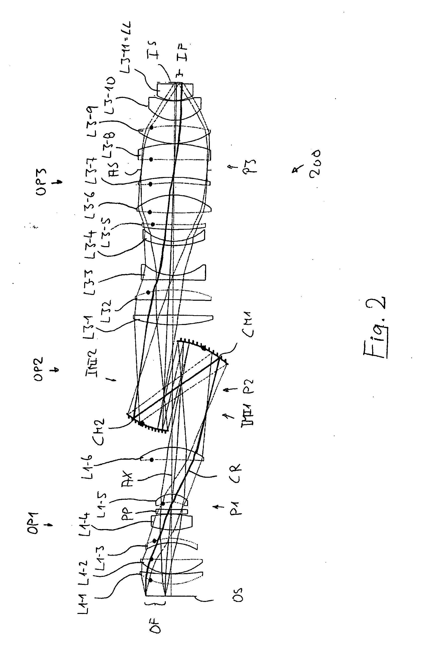
[0073] Whereas the general layout is similar to the embodiment of FIG. 2, there are some remarkable differences. For example, the first objective part OP1, which has six lenses L1-1 to L1-6 and an additional plane plate PP adjacent to the first pupil surface P1, has positive lenses only, where three positive lenses L1-1, L1-3 and L1-6 are biconvex, thereby providing strong refractive power to collect the rays. The number of lenses is reduced to nine lenses in the third objective part OP3 such that the overall number of lenses is NL=15. Biconvex positive lens L3-1 immediately following the second intermediate image IM12 is the largest lens (Dmax=187.55 mm). At Y′=15.83 the condition COMP=15.299 holds and Dmax / NA=213.1 mm. A comparison with data for projection objective 200 reveals that a...

third embodiment

[0074]FIG. 4 shows projection objective 400 designed as a dry objective for operating wavelength λ=248 nm, having NA=0.93 and image field size 26 mm*5.5 mm. The specification is given in tables 4, 4A.

[0075] The projection objective 400 has only five lenses (in addition to an optional plane parallel PP) in the first objective part OP1. Specifically, the first objective part OP1 has a biconvex positive lens L1-1 having an aspheric entrance surface immediately adjacent to the object surface OS, a positive meniscus lens L1-2 concave towards the image-side, a biconvex positive lens L1-3 following with a small air space, a parallel plate PP adjacent to the first pupil surface P1, a positive lens L1-4 having almost flat entrance surface and aspheric exit surface and a positive meniscus lens L1-5 concave and aspheric on the entrance side. All of these lenses L1-1 to L1-5 are positive lenses, including two biconvex lenses L1-1 and L1-3 and two meniscus lenses L1-2 and L1-5. The third objecti...

fourth embodiment

[0076]FIG. 5 shows projection objective 500 designed as a dry objective for operating wavelength λ=248 nm, having NA=0.93 and image field size 26 mm*5.5 mm. The specification is given in tables 5, 5A.

[0077] A comparison between projection objective 400 and 500 shows that the number of lenses is further reduced in the first objective part OP1. Projection objective 500 may be derived from projection objective 400 by combining the optical action of lenses L1-2 and L1-3 of projection objective 400 to form a single, relatively thick biconvex lens L1-2 in projection objective 500. Corresponding adjustments to surface shape and position are made predominantly in the other lenses of the first objective part. The optimization reduces the number of lenses to four positive lenses in objective part OP1, such that NL=14.


PUM


Abstract

A reduction projection objective for projection lithography has a plurality of optical elements configured to image an effective object field arranged in an object surface of the projection objective into an effective image field arranged in an image surface of the projection objective at a reducing magnification ratio |β|<1. The optical elements form a dry objective adapted with regard to aberrations to a gaseous medium with refractive index n′<1.01 filling an image space of finite thickness between an exit surface of the projection objective and the image surface. The optical elements include a largest lens having a maximum lens diameter Dmax and are configured to provide an image-side numerical aperture NA<1 in an effective image field having a maximum image field height Y′. With COMP=Dmax/(Y′·(NA/n′)2) the condition COMP<15.8 holds. Preferred embodiments have relatively small overall numbers of lenses which allows to fabricate the projection objectives relatively small in size with relatively low material consumption, yielding high performance, light weight, compact reduction projection objectives for dry lithography.

Description

[0001] This application claims the benefit of U.S. Provisional Application No. 60 / 786,361, filed on Mar. 28, 2006. The disclosure of this Provisional Application is incorporated herein by reference.BACKGROUND OF THE INVENTION [0002] 1. Field of the Invention [0003] The invention relates to a projection objective for imaging an effective object field arranged in an object surface of the projection objective onto an effective image field arranged in an image surface of the projection objective and a projection exposure apparatus including such projection objective. [0004] 2. Description of the Related Art [0005] Projection objectives are, for example, employed in projection exposure apparatuses used for fabricating semiconductor devices and other types of micro devices and serve to project patterns on photomasks or reticles, hereinafter referred to generically as “masks” or “reticles,” onto an object having a photosensitive coating with ultrahigh resolution on a reduced scale. [0006] ...

Claims


Application Information

Patent Timeline
IPC IPC(8): G02B27/18G02B17/08
CPCG02B13/143G03F7/70225G02B17/0812
Inventor ULRICH, WILHELMDODOC, AURELIANFELDMANN, HEIKOROSTALSKI, HANS-JUERGEN
Owner CARL ZEISS SMT GMBH
Why Eureka
Try Eureka