Friction stir fabrication

a technology of friction stir and fabrication method, which is applied in the direction of manufacturing tools, applications, cooking vessels, etc., can solve the problems that conventional techniques are not suitable for processing many types of substrates and coating materials, and achieve the effects of reducing oxide content, superior bond strength, and density

Inactive Publication Date: 2008-02-21
MELD MFG CORP
View PDF9 Cites 76 Cited by
  • Summary
  • Abstract
  • Description
  • Claims
  • Application Information

AI Technical Summary

Benefits of technology

[0005] One embodiment of the present invention provides a low-temperature friction-based coating method termed friction stir fabrication (FSF), in which material is deposited onto a substrate and subsequently stirred into the substrate using friction stir processing to homogenize and refine the microstructure. This solid-state process is capable of depositing coatings, including nanocrystalline aluminum and/or metal matrix composites and the like, onto substrates such as aluminum at relatively low temperatures. For

Problems solved by technology
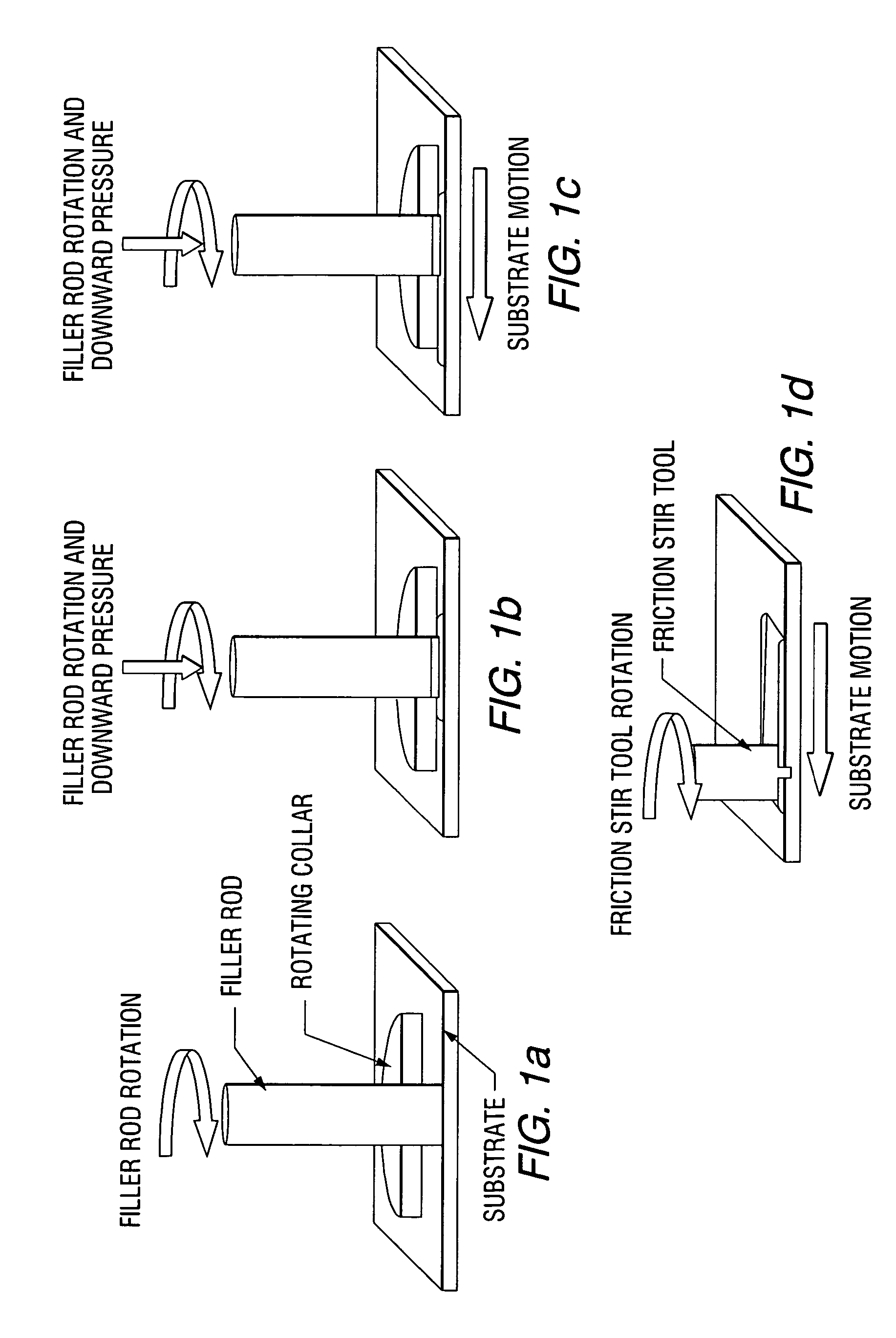
Such conventional techniques are not suitable for processing many types of substrates and coating materials, such as nanocr

Method used


Image

  • Friction stir fabrication
  • Friction stir fabrication
  • Friction stir fabrication

Examples


example 1

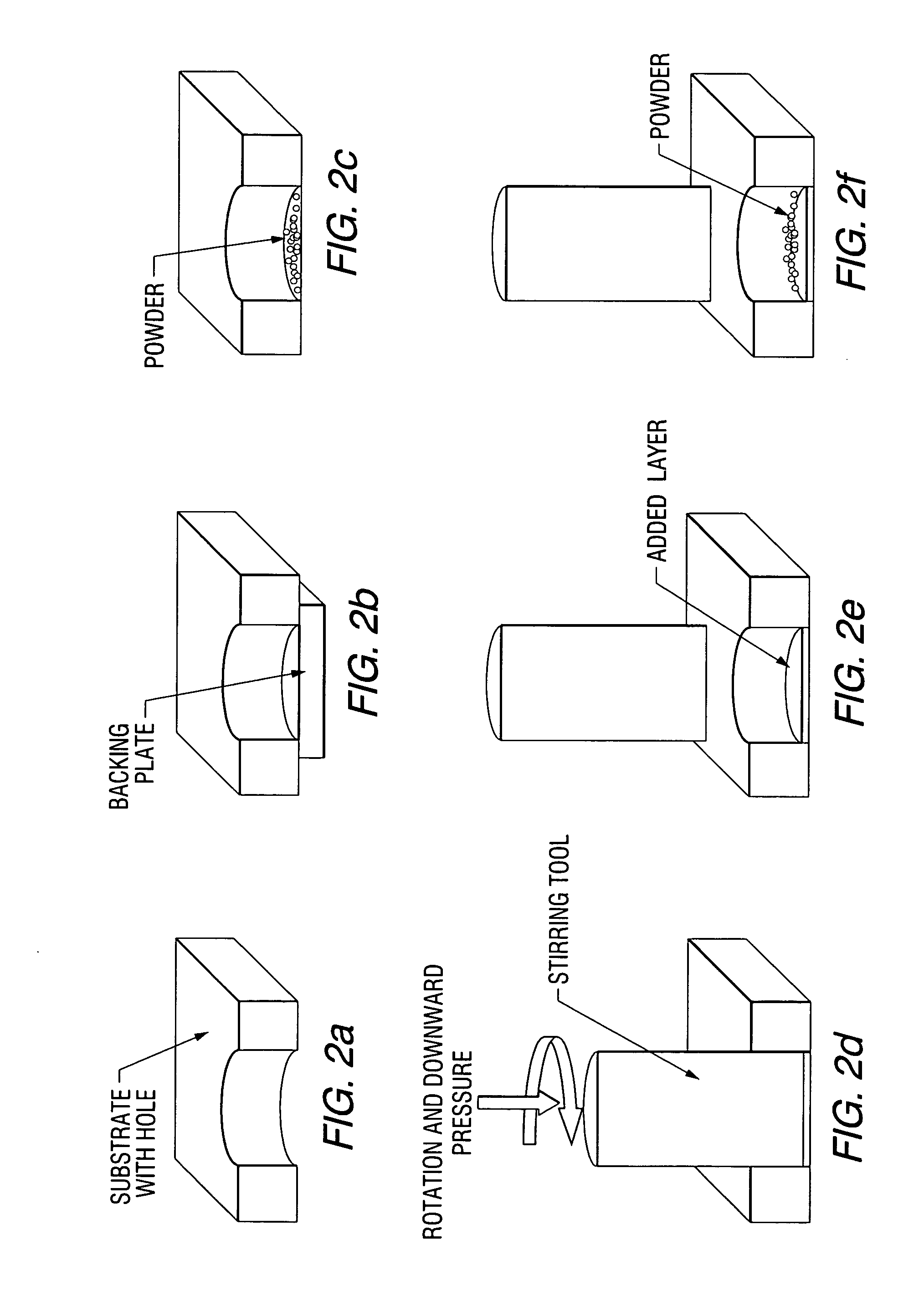
[0047] 5083 Al plate was coated with nanocrystalline aluminum deposit. Because the nanocrystalline Al was a limited supply and in powder form, the coating deposit was made using the “hole-filling” method and the interface at the bottom of the hole was the interface of interest. FIG. 4 shows representative stress-strain curves for bulk 5083 Al, and the 5083 Al substrate with nanocrystalline Al coating. The micrographs of FIGS. 5 and 6 show the interfacial region between the substrate and the deposit as polished and etched, respectively. The microstructure in the nanocrystalline region is very fine while the 5083 is characterized by large precipitates and large high aspect ratio grains.

[0048] Consolidated deposits of nanocrystalline Al powder are preferably homogenous and fully dense. All of the 5083 Al-nanocrystalline Al tensile specimens tested failed at or near the interface at approximately 75-95% of the bulk 5083 ultimate tensile strength, indicating that metallurgical bonding o...

example 2

[0050] An aluminum substrate was coated with an Al—SiC metal matrix composite. SiC-powder-filled 6063 Al tubes were used as the deposition material for samples with an Al—SiC MMC coating. The matrix for the MMC coating may be commercially pure (CP) Al, however, CP Al tubes of the desired diameter may not be readily available. Therefore, 6063 T5 Al tubes may be substituted for CP Al tubes for this demonstration. 6063 Al was selected because it contains silicon, which limits the dissolution of silicon from the silicon carbide reinforcement. Such dissolution would lead to the formation of Al4C3, a detrimental brittle phase. The average particle size (APS) of the SiC powder used was 1 mm and the volume fraction of SiC in the composites was approximately 10 vol. %.

example 3

[0051] A 5083 Al plate was coated with an Al—SiC metal matrix composite. To test the bond strength between 5083 Al and 6063 Al—SiC (10 v %), a ½-inch thick MMC coating was deposited on a 5083 Al substrate using FSF with SiC filled 6063 Al T5 tubes as the feed rod. FIG. 7 shows a stress-strain curve for the 5083 Al substrate and the interface between the substrate and the Al—SiC metal matrix composite coating. A cross-section of the polished MMC coating and substrate are shown on the right side of FIG. 8. Significant improvements in both the coating and interfacial microstructure have been made. The improvements primarily result from the use of a threaded-tapered stirring tool for post-deposition friction stir processing. A friction stir processing pass was made (the stirring tool translated normal to the cross-section shown in the micrograph) after each incremental increase in the coating thickness of approximately ⅛-inch. As is evident from the micrograph, the friction stir process...


PUM

PropertyMeasurementUnit
Temperatureaaaaaaaaaa
Angleaaaaaaaaaa

Abstract

A low-temperature friction-based coating method termed friction stir fabrication (FSF) is disclosed, in which material is deposited onto a substrate and subsequently stirred into the substrate using friction stir processing to homogenize and refine the microstructure. This solid-state process is capable of depositing coatings, including nanocrystalline aluminum and/or metal matrix composites and the like, onto substrates such as aluminum at relatively low temperatures. A method of making rod stock for use in the FSF process is also disclosed.

Description

CROSS-REFERENCE TO RELATED APPLICATION [0001] This application claims the benefit of U.S. Provisional Patent Application Ser. No. 60 / 720,521 filed Sep. 26, 2005, which is incorporated herein by reference.GOVERNMENT CONTRACT [0002] The present invention was supported by the United States Office of Naval Research under Contract No. N00014-05-1-0099. The United States Government has certain rights in this invention.FIELD OF THE INVENTION [0003] The present invention relates to friction stir fabrication, and more particularly relates to coating, surface modification and repair of substrates using friction stirring techniques, as well as the production of friction stir rod stock. BACKGROUND INFORMATION [0004] Conventional thermal spray coating techniques, such as flame spray, high-velocity oxygen fuel (HVOF), detonation-gun (D-Gun), wire arc and plasma deposition, produce coatings that have considerable porosity, significant oxide content and discrete interfaces between the coating and s...

Claims


Application Information

Patent Timeline
IPC IPC(8): A47J36/02
CPCB22F2998/00B23K20/1225B23K20/1275B23K20/128C23C24/045C23C24/06C23C26/00C22C29/00C22C32/00
Inventor CREEHAN, KEVINSCHULTZ, JEFFREY PATRICK
Owner MELD MFG CORP
Why Eureka
Try Eureka