
Focused ion beam apparatus and sample section forming and thin-piece sample preparing methods

a technology of focused ion beam and sample section, which is applied in the field of forming sample section and working tem sample, can solve the problem of taking time in the transition period

Active Publication Date: 2008-02-21
HITACHI HIGH TECH SCI CORP
View PDF3 Cites 17 Cited by
  • Summary
  • Abstract
  • Description
  • Claims
  • Application Information

AI Technical Summary

Benefits of technology

[0015] As described above, according to a focused ion beam apparatus of the invention and sample section forming method using the focused ion beam apparatus, by terminating etching through detecting a signal amount change of a generated secondary charged particle while performing etching, a defect or a contact-hole center position seen from above can be detected even with an FIB apparatus not having a SEM observation function, thus forming a sample section with efficiency. Meanwhile, according to the focused ion beam apparatus of the invention and thin-piece sample preparing method using the focused ion beam apparatus, a thin-piece sample for TEM-observation can be efficiently prepared in the center of which a defect or the center axis of a contact-hole lies, even in an FIB apparatus not having a SEM observation function.

Problems solved by technology

Meanwhile, because of working with an FIB and confirming an end point by switching the irradiation beam to SEM, it takes time in switchover.

Method used


Image

  • Focused ion beam apparatus and sample section forming and thin-piece sample preparing methods
  • Focused ion beam apparatus and sample section forming and thin-piece sample preparing methods
  • Focused ion beam apparatus and sample section forming and thin-piece sample preparing methods

Examples


Embodiment Construction

[0025] Based on FIGS. 1 to 7, explanation will be now made on an embodiment of the present invention.

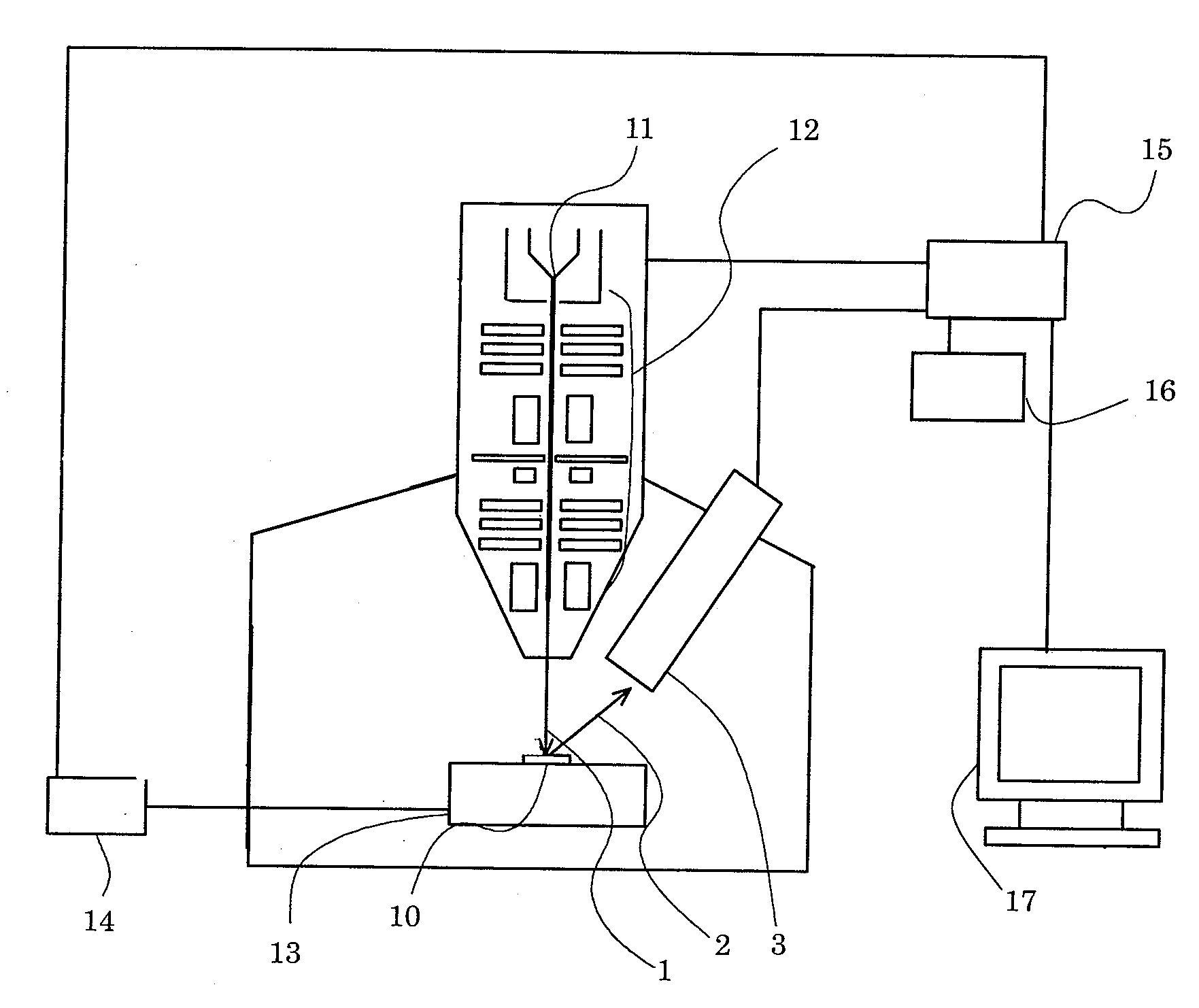
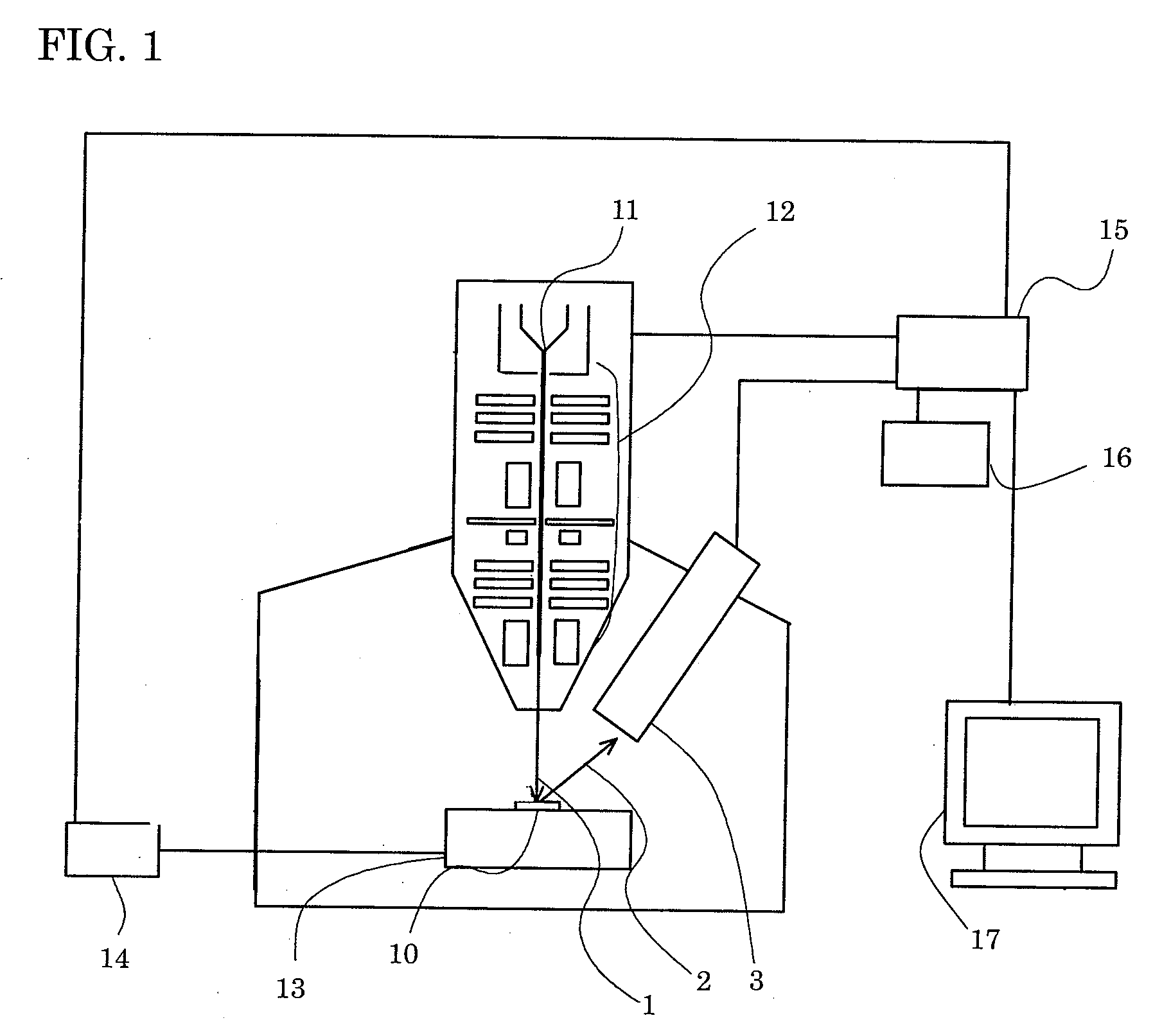
[0026]FIG. 1 is a schematic diagram of an FIB apparatus showing an embodiment of the invention. The ions, generated by the ion source 11, are collected by an ion optical system 12 into a focused ion beam 1 and scan-irradiated to a sample 10 like a semiconductor device. The sample 10, rested on a sample stage 13, can be moved by a stage drive mechanism 14. The secondary electron 2, that is a secondary charged particle generated by irradiating a focused ion beam 1 to the sample 10, is to be detected by a secondary electron detector 3 serving as a secondary charge detector. From the signal of a secondary electron detected, a secondary electron image of the sample 10 is to be displayed on a display 17. Meanwhile, an end-point detecting mechanism 16 can detect an end point depending upon a change amount from the detected signal amount of secondary electrons during working.

[0027] Using F...


PUM

PropertyMeasurementUnit
TEMaaaaaaaaaa
defect analysisaaaaaaaaaa
end-to-end distanceaaaaaaaaaa

Abstract

Detected is a secondary electron generated by irradiating a focused ion beam while performing etching a sample section and the around through scan-irradiating the focused ion beam. From a changing amount of the detected secondary electron signal an end-point detecting mechanism detects an end point to thereby terminate the etching, so that a center position of a defect or a contact hole is effectively detected even with an FIB apparatus not having a SEM observation function.

Description

[0001] This application claims priority under 35 U.S.C. §119 to Japanese Patent Application No. JP2006-224191 filed Aug. 21, 2006, the entire content of which is hereby incorporated by reference. BACKGROUND OF THE INVENTION [0002] The present invention relates to forming a sample section and working a TEM sample by use of a focused ion beam apparatus. [0003] Using FIG. 9, explanation is made on an observation method of working a defect region with use of a conventional FIB-SEM apparatus. At first, a sample 22 is worked by irradiating an ion beam IB, to form a rectangular opening 21. After forming the opening, an electron beam EB is scan-irradiated to a section D. By detecting a secondary electrons generated at that time, a secondary electron image is observed as to the section D. In order to acquire a section through a defect center in defect analysis, two points are specified in an end of a particular structure within an acquired secondary electron image. Then, the particular struc...

Claims


Application Information

Patent Timeline
Patent Type & Authority Applications(United States)
IPC IPC(8): G01N23/00
CPCG01N1/32G01N23/2255G01N2223/104G01N2223/32G01N2223/611H01J2237/31749H01J37/3045H01J37/3056H01J2237/30466H01J2237/30488H01J2237/31745H01J37/3005
Inventor TASHIRO, JUNICHIIKKU, YUTAKAFUJII, TOSHIAKI
Owner HITACHI HIGH TECH SCI CORP
Learn More