Coatings Comprising Carbon Nanotubes

a technology of carbon nanotubes and coatings, applied in the direction of electrically conductive paints, nanoinformatics, semiconductor/solid-state device details, etc., can solve the problems of difficult application of dry process fabrication of electrically conductive coatings to continuous or large substrates, complicated apparatuses having vacuum systems, and inability to permit real-time marking of substrates. to achieve the effect of reducing discoloration and surface textur

Inactive Publication Date: 2008-02-21
DOUGLAS JOEL S
View PDF6 Cites 94 Cited by
  • Summary
  • Abstract
  • Description
  • Claims
  • Application Information

AI Technical Summary

Benefits of technology

[0009] Therefore, a need has arisen for an electrically conductive translucent ink, dyes or coating comprised of conductive materials formed from a dispersion with low solids concentrations and that will form a smooth surface morphology after it is applied to a substrate and cured. The conductive translucent ink, dyes or coating formed by using carbon nanotubes that overcome the problems of rough surface morphologies caused by high solids concentrations found in conductive coatings manufactured from methods described in the related prior art minimize discoloration and surface texture roughness of the cured conductive ink, dyes or coating.

Problems solved by technology

However, the dry process requires a complicated apparatus having a vacuum system and deposition process and does not permit the real time marking of a substrate because of the need to be done in a vacuum.
As described in the textbook Handbook of Materials and Processes for Electronics, dry process fabrication of electrically conductive inks and coatings is difficult to apply to a continuous or large substrate such as in a large converting process because of the cost of forming the vacuum chambers.
This dispersion has a high solids concentration that creates a rougher surface texture to achieve higher conductivity due to the need to increase the concentration of conductive particles, which also results in low translucent properties.
However, the thin layer embodiments have limited conductive properties.
The loss of these properties limits the usefulness of the resulting conductive coatings for those applications requiring good translucent and smooth surface morphology properties such as devices used in co-pending provisional applications U.S. 60 / 546,762 strip electrode with conductive nanotube printing and U.S. 60 / 652,111 Taser personnel armor and co-pending application Ser. No. 11 / 029,270 Security marking and security mark, the disclosures of which are incorporated herein by reference in their entirety.
However the clarity and smoothness of the surface morphology is limited by the high percentage of MWNT in the conductive ink and coating which makes the coating appear grey to black and the surface roughness is 384 nm using an Optical Profilometer.

Method used


Image

  • Coatings Comprising Carbon Nanotubes
  • Coatings Comprising Carbon Nanotubes
  • Coatings Comprising Carbon Nanotubes

Examples


examples

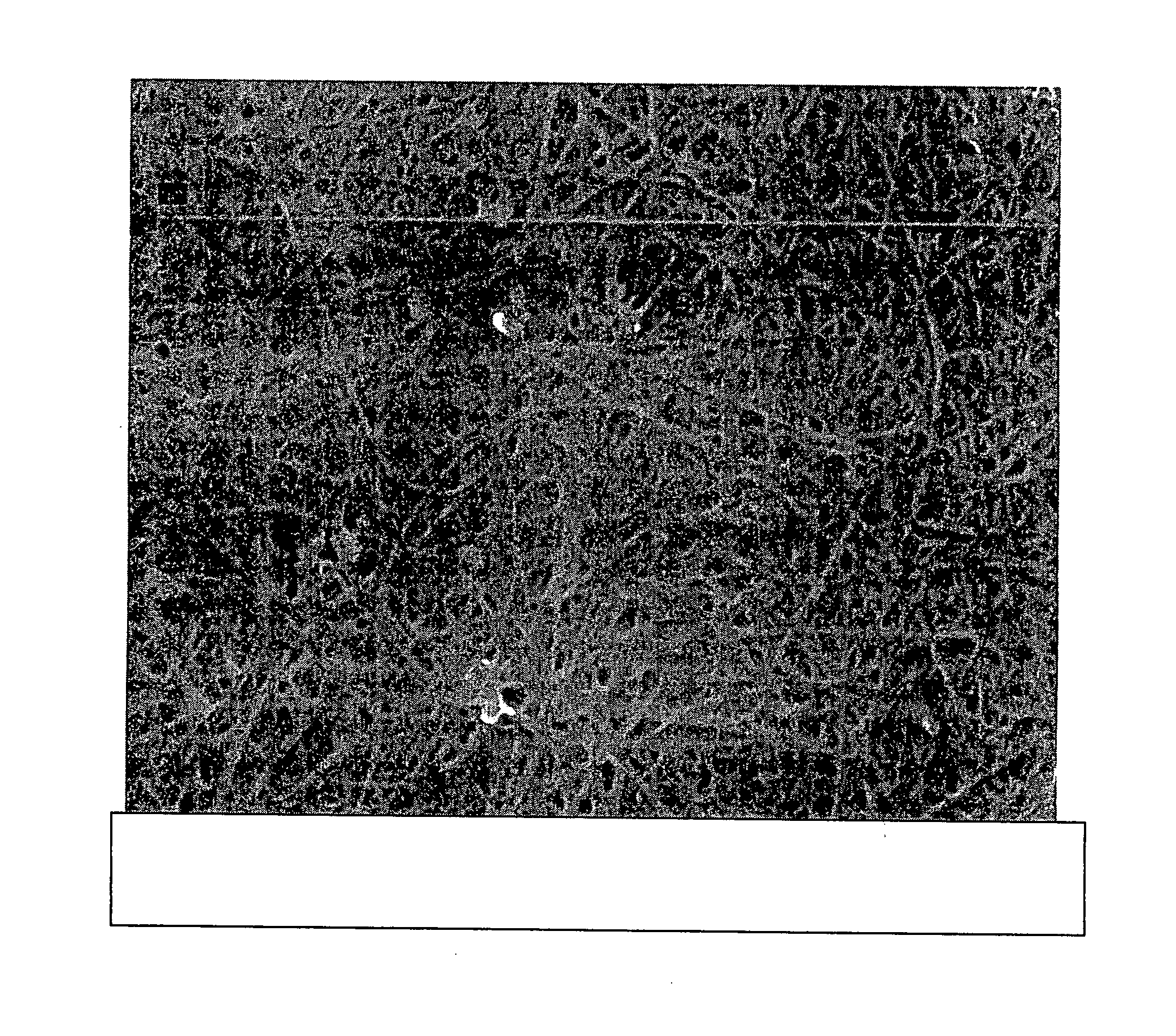
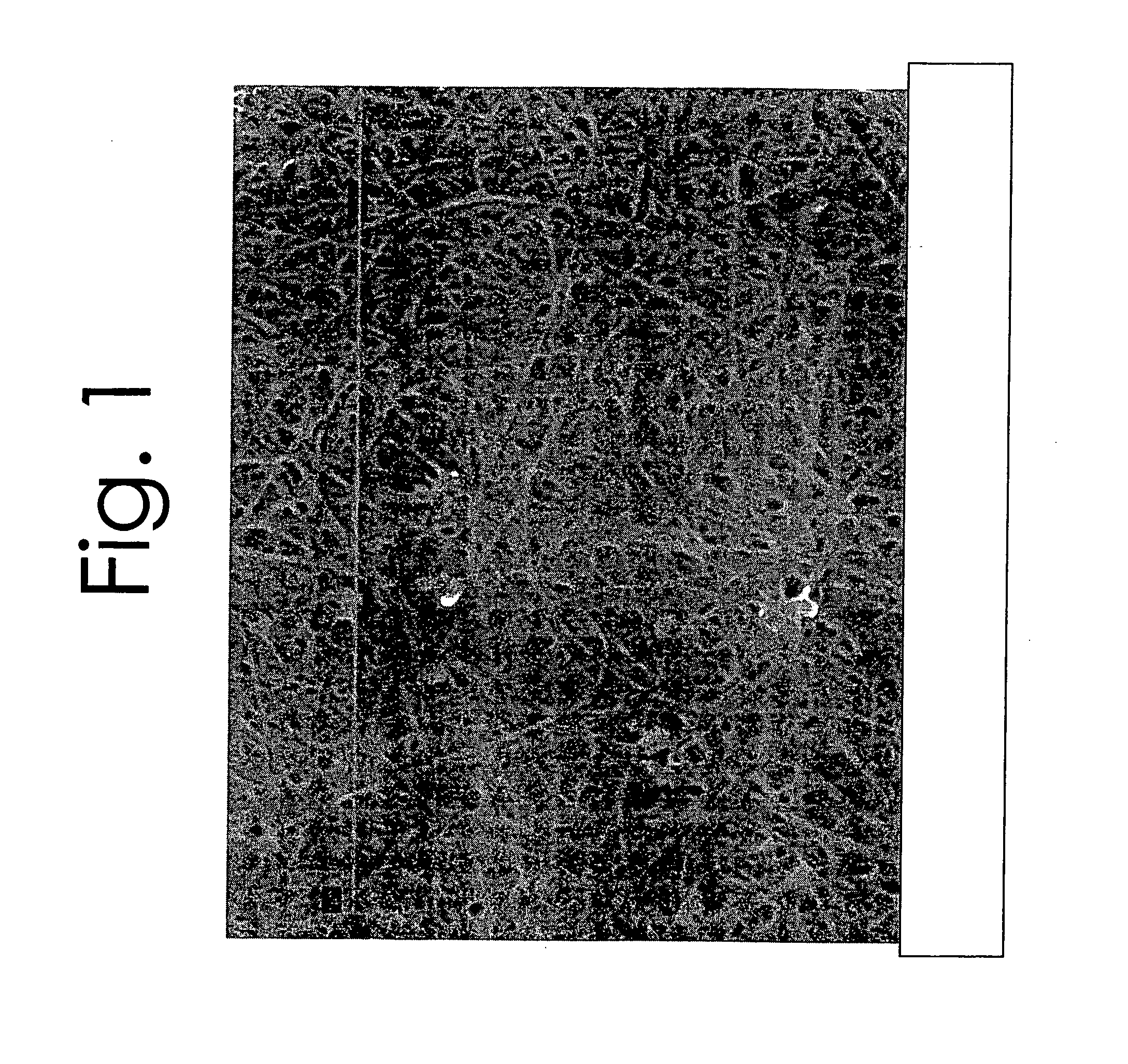
[0080]FIG. 1 is a picture of carbon nanotube mat formed by curing.

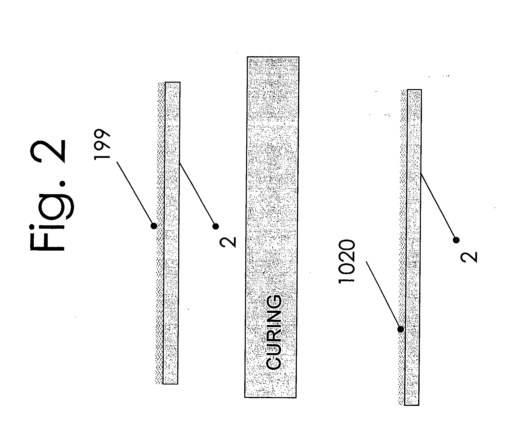
[0081]FIG. 2 shows CNT inks or dispersion coated on Polyester. The conductive inks and coatings are formed by coating the conductive ink (199) on a flexible film (2). The ink can be formed from single-walled or multi walled nanotubes and may be formed from multiple layers or dispersions containing, carbon nanotubes, polymers, carbon nanotubes / antimony tin oxide, carbon nanotubes / platinum, or carbon nanotubes / silver or carbon nanotubes / silver-chloride. This forms conductive material (1020) when cured properly.

[0082]FIG. 3 shows a two part CNT ink or dispersion forming a conductive material of the invention. The coated carbon nanotubes layer 1005 is applied to the Polyester layer 2 and cured. The separate protective polymer coating 1010 is applied to cured carbon nanotube layer 1005 and Polyester (2) and then cured. The coated carbon nanotubes layer 1005 can be formed from one or more individual coating and curing ste...


PUM

PropertyMeasurementUnit
outer diameteraaaaaaaaaa
surface roughnessaaaaaaaaaa

Abstract

An electrically conductive coating is disclosed. According to one embodiment of the present invention, the coating includes a plurality of single-wall or multi-walled Carbon nanotubes having a diameter less than 20 nanometers. The disclosed coating demonstrates excellent conductivity and smooth surface morphology. Methods of preparing the coating as well as methods of its use are also disclosed herein.

Description

CROSS REFERENCE TO RELATED APPLICATIONS [0001] This application claims priority to U.S. Provisional Application No. 60 / 576,195, filed on Jun. 2, 2004, entitled Coatings Comprising Carbon Nanotubes and Antimony-Tin Oxide, the disclosure of which is incorporated herein by reference in its entirety.FIELD OF THE INVENTION [0002] The present invention relates to electrically conductive coatings, dyes and inks formed from conductive dispersions. More particularly, the invention relates to low solids concentration electrically conductive coatings, dyes and inks comprised of carbon nanotubes, dispersions of carbon nanotubes and conductive oxides, and to composite coatings formed from dispersions of carbon nanotubes, conductive metal oxide and polymer binders. The conductive carbon nanotube layer is formed by depositing the coating, dye or ink containing carbon nanotube dispersion onto a non conductive substrate. BACKGROUND OF THE INVENTION [0003] Electrically conductive ink and coatings are...

Claims


Application Information

Patent Timeline
Patent Type & Authority Applications(United States)
IPC IPC(8): C09D11/00C08J7/044C09D5/24H01B1/24H01L23/498H01L23/52H01L51/00H01L51/30
CPCB82Y10/00Y10T428/269C08J7/047C08J2367/02C08J2475/04C09D5/24C09D11/30C09D11/52H01B1/24H01L23/49877H01L51/0048H01L51/0052H01L2924/0002C08J7/045H01L2924/00C08J7/0423C08J7/0427C08J7/044H10K85/221H10K85/615
Inventor DOUGLAS, JOEL S.
Owner DOUGLAS JOEL S
Why Eureka
Try Eureka