Fuel Cell System

a fuel cell and system technology, applied in the field of fuel cell systems, can solve the problems of disadvantageous deterioration of the catalyst layer, sometimes unsuitable method for compact distributed power sources for automobiles, etc., and achieve the effect of suppressing deterioration caused at system shutdown as well as during storag

Inactive Publication Date: 2008-02-21
NISSAN MOTOR CO LTD
View PDF3 Cites 9 Cited by
  • Summary
  • Abstract
  • Description
  • Claims
  • Application Information

AI Technical Summary

Benefits of technology

[0009] As described above, by utilizing the fact that less water content in a catalyst layer on the oxidant electrode side of a fuel cell results in less deterioration of the catalyst layer caused when operation of the fuel cell is stopped, the fuel cell system according to the present invention first stops supplying the fuel gas to the fuel electrode of the fuel cell at system shutdown and at the same time starts supplying a dry oxidant gas such as air (the same or lower humidity than that of the outside air) to the oxidant electrode, so as to reduce the water content in the catalyst layer of the oxidant electrode side. The fuel cell system of the present invention thereafter stops operations after supplying the oxidant gas such as air also to the fuel electrode to replace the fuel gas in the fuel electrode with the oxidant gas, so that deterioration caused at system shutdown as well as during storage can be suppressed.
[0010] According to the fuel cell system of the present invention, the supply of a fuel gas to the fuel electrode of the fuel cell is stopped at system shutdown, and at the same time the supply of a dry oxidant gas to the oxidant electrode is started, and subsequently this dry oxidant gas is supplied also to the fuel electrode before the system operation is stopped. This can effectively suppress deterioration of the proton exchange membrane and catalyst layer of the fuel cell which is caused at the time of system shutdown or during storage, and also improve handleability during storage.

Problems solved by technology

As disclosed in Japanese Patent Application Laid-Open No. 2002-313394, however, when the fuel cell system shuts down in a state that hydrogen and air still remain in the fuel electrode and the oxidant electrode, respectively, of the fuel cell, a catalyst layer is disadvantageously deteriorated because the fuel cell is maintained at a high electrical potential or because air comes into the fuel electrode from inside and outside the fuel cell.
However, such a method sometimes is not suitable for a compact distributed power source for automobiles and the like, from a safety standpoint and when the storage period is long.

Method used


Image

  • Fuel Cell System
  • Fuel Cell System
  • Fuel Cell System

Examples


first embodiment

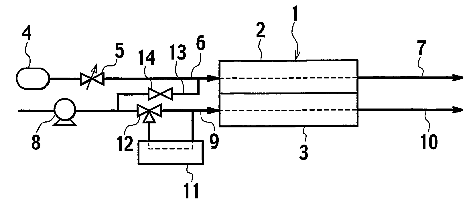
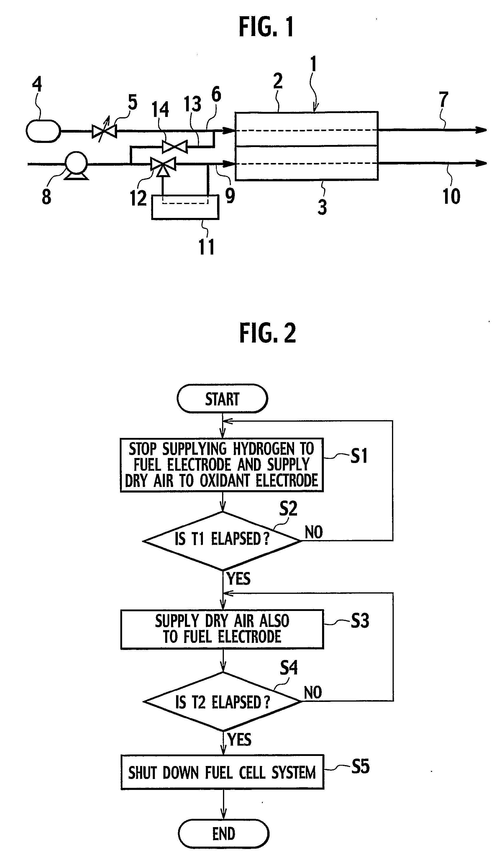
[0019]FIG. 1 is a diagram showing a schematic configuration of a fuel cell system according to a first embodiment to which the present invention is applied.

[0020] The fuel cell system according to this embodiment includes a fuel cell stack 1 formed by stacking a plurality of fuel cells each of which uses, for example, a proton exchange membrane as an electrolyte. Each cell that constitutes the fuel cell stack 1 has a fuel electrode 2 as an anode and an oxidant electrode 3 as a cathode, and generates electricity when a fuel gas of hydrogen is supplied from a fuel gas supply system to the fuel electrode 2 and an oxidant gas of air is supplied from an oxidant gas supply system to the oxidant electrode 3.

[0021] The fuel gas supply system has, for example a fuel tank 4 in which hydrogen is stored, and delivers hydrogen in the fuel tank 4 via a fuel supply amount regulating valve 5 through a fuel gas supply pipe 6 into the fuel cell stack 1 so as to supply hydrogen to the fuel electrode...

second embodiment

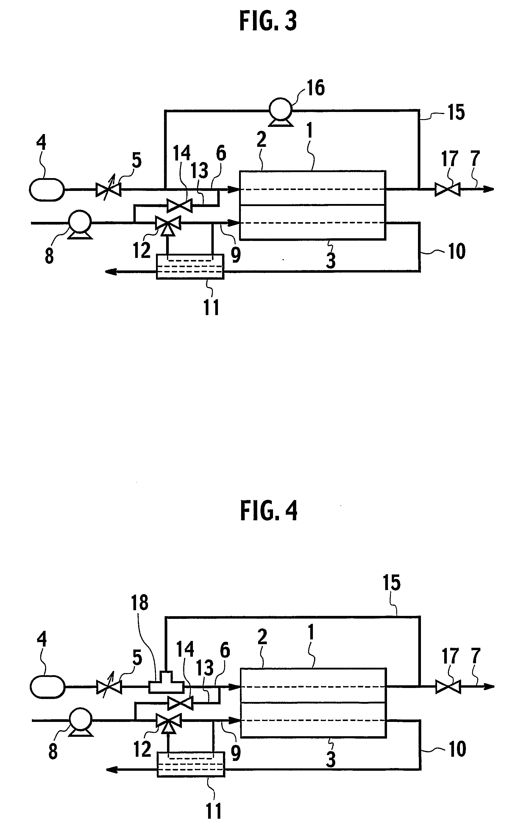
[0029]FIG. 3 is a diagram showing a schematic configuration of a fuel cell system according to a second embodiment to which the present invention is applied.

[0030] The fuel cell system of this embodiment is configured as a fuel cell system employing a fuel circulation method of circulating and reusing redundant hydrogen discharged from the fuel cell stack 1, and is additionally provided with a fuel gas circulating pipe 15 that is used to circulate and reuse hydrogen, between the fuel gas exhaust pipe 7 and the fuel gas supply pipe 6 so as to connect the outlet side of the fuel electrode 2 with the inlet side thereof in the fuel cell stack 1. In the midway part of this fuel gas circulating pipe 15, a circulating pump 16 is disposed which is used to forcibly return, to the fuel gas supply pipe 6, redundant hydrogen unused for electricity generation in the fuel cell stack 1 and thus discharged therefrom. Furthermore, a switching valve 17 is provided downstream from the branch point of...

third embodiment

[0035]FIG. 5 is a diagram showing a schematic configuration of a fuel cell system according to a third embodiment to which the present invention is applied.

[0036] The fuel cell system in this embodiment has the configuration described in the second embodiment and additionally includes charge consumption means 19 for consuming electric charge generated in the fuel cell stack 1 during the operation of system shutdown, voltage detection means 20 for detecting voltage of the fuel cell stack 1, temperature detection means 21 for detecting temperature of cells that constitute the fuel cell stack 1, and resistance measurement means 22 for measuring resistance of cells that constitute the fuel cell stack 1. Other components of the fuel cell system in this embodiment are the same as those in the second embodiment.

[0037] The charge consumption means 19 is connected both to the end of the fuel electrode 2 and to the end of the oxidant electrode 3 through a switch (not shown). When this switc...


PUM

PropertyMeasurementUnit
voltageaaaaaaaaaa
flow rateaaaaaaaaaa
charge consumptionaaaaaaaaaa

Abstract

At system shutdown, supply of hydrogen to a fuel electrode of a fuel cell stack is stopped, and at the same time dry air is supplied to an oxidant electrode. The dry air is subsequently supplied also to the fuel electrode, and finally the system is shut down. This allows optimal conditioning of a fuel cell at system shutdown, and effectively suppresses deterioration of a proton exchange membrane or a catalyst layer of the fuel cell which is caused at system shutdown as well as during storage. Furthermore, a fuel cell system excellent in safety and the like can be provided.

Description

TECHNICAL FIELD [0001] The present invention relates to a fuel cell system including fuel cells, and more particularly, to an improvement in control during a system shutdown. BACKGROUND ART [0002] As a countermeasure to recent environmental problems, especially to air pollution caused by automobile exhaust gas and global warming stemming from carbon dioxide emissions, much attention is focused on fuel cell technology which achieves clean exhaust emissions and offers high energy efficiency. A fuel cell is an energy conversion system in which hydrogen or hydrogen-rich reformed gas as fuel is supplied together with air to an electrolyte / electrode catalyst composite to cause an electrochemical reaction so that chemical energy is converted to electrical energy. In particular, a solid polymer electrolyte fuel cell that uses a proton exchange membrane as an electrolyte is inexpensive and easily reducible in size, and further has high power density, therefore, applications to power sources ...

Claims


Application Information

Patent Timeline
Patent Type & Authority Applications(United States)
IPC IPC(8): H01M8/04
CPCH01M8/04126H01M8/04223Y02T90/32Y02E60/50H01M2250/20Y02T90/40H01M8/04228H01M8/04225
Inventor SHIMOI, RYOICHI
Owner NISSAN MOTOR CO LTD
Why Eureka
Try Eureka