Geothermal Cooling Device

a cooling device and geothermal technology, applied in the field of geothermal cooling systems, can solve the problems of high capital and installation costs, low adoption rate in the commercial marketplace, and relatively high cost, and achieve the effect of efficient cooling an indoor spa

Inactive Publication Date: 2008-03-06
FREE ENERGY SOLUTIONS
View PDF24 Cites 23 Cited by
  • Summary
  • Abstract
  • Description
  • Claims
  • Application Information

AI Technical Summary

Benefits of technology

[0019] In another embodiment, a simple cooling device not requiring a thermostat or switch is suitable for coupling to a thermal superconductor geothermal ground coil extending below a ground level allowing passive thermal conduction to an earth source and for connecting to a power source. The cooling device includes a thermal superconductor having a first end couplable to said thermal superconductor geothermal ground coil

Problems solved by technology

Even though ground source heat pump systems achieve efficiencies of up to 350% compared to less than 100% for most conventional systems, they have achieved a very low level of adoption in the commercial marketplace because their capital costs and installation costs have been much higher than conventional systems.
These high capital and installation costs have largely been due to fundamental inefficiencies in the ground loop subsystem.
Few installations have sufficient available land for trenching so loops are most commonly installed in deep holes and this makes them relatively expensive for several reasons.
Holes of this size are relatively expensive to drill and require heavy equipment that disrupts landscaping, making it expensive to retrofit existing homes.
Holes of this size also leave large voids around the loop that should be filled with materials such as bentonite clay in order for heat to transfer from the ground to the loop, which adds significantly to the cost of installation.
Second, having both supply and return lines in the same hole results in thermal “short circuiting” which reduces the efficiency of the loop.
This lowers the efficiency of the loop so the loop should be made longer to compensate, adding to the cost of drilling and piping.
This consumes a significant amount of electric energy, lowering the overall efficiency of the system.
Third, the copper pipes used in direct geoexchange transfer heat more efficiently to and from the gro

Method used


Image

  • Geothermal Cooling Device
  • Geothermal Cooling Device
  • Geothermal Cooling Device

Examples


Embodiment Construction

)

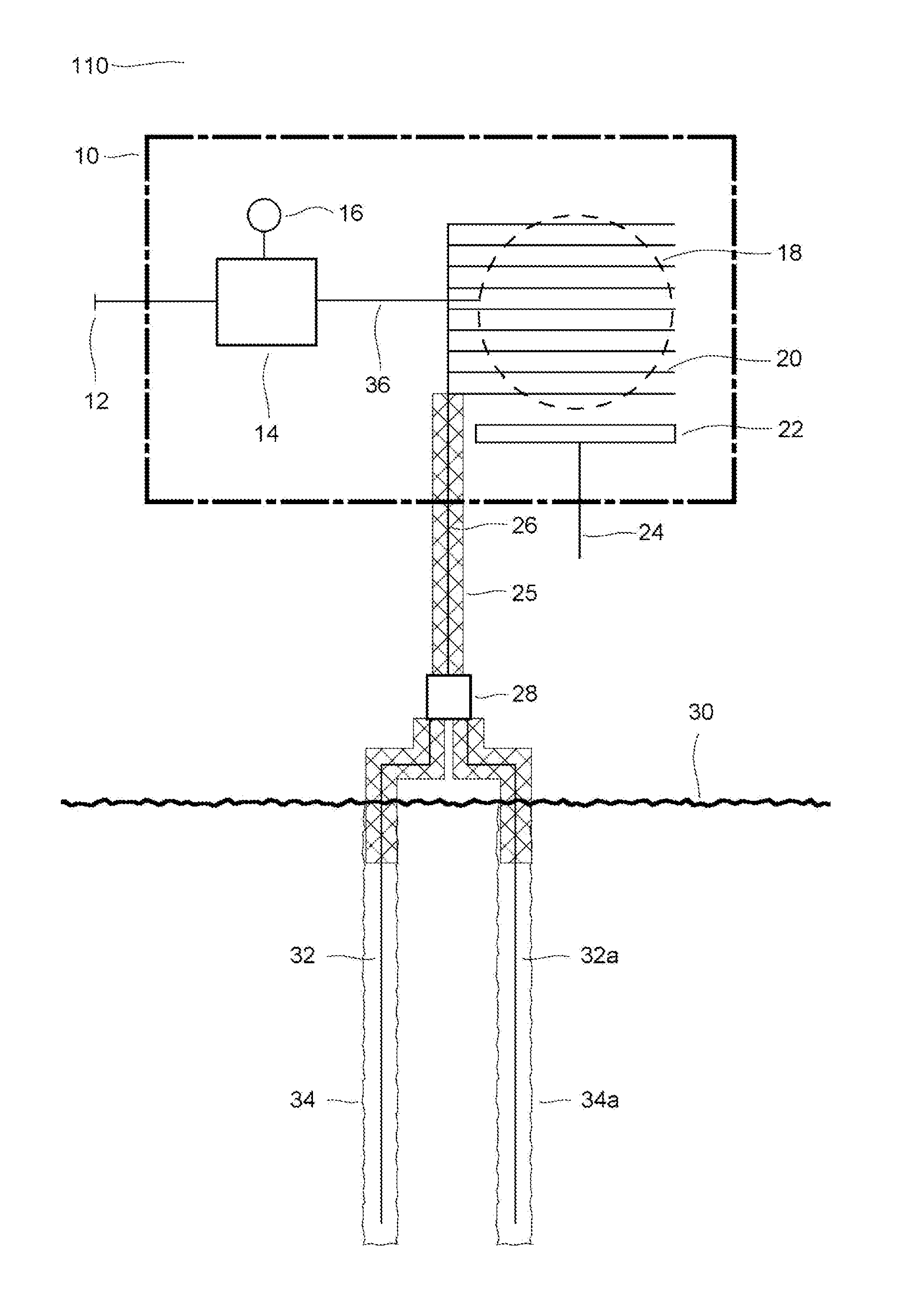
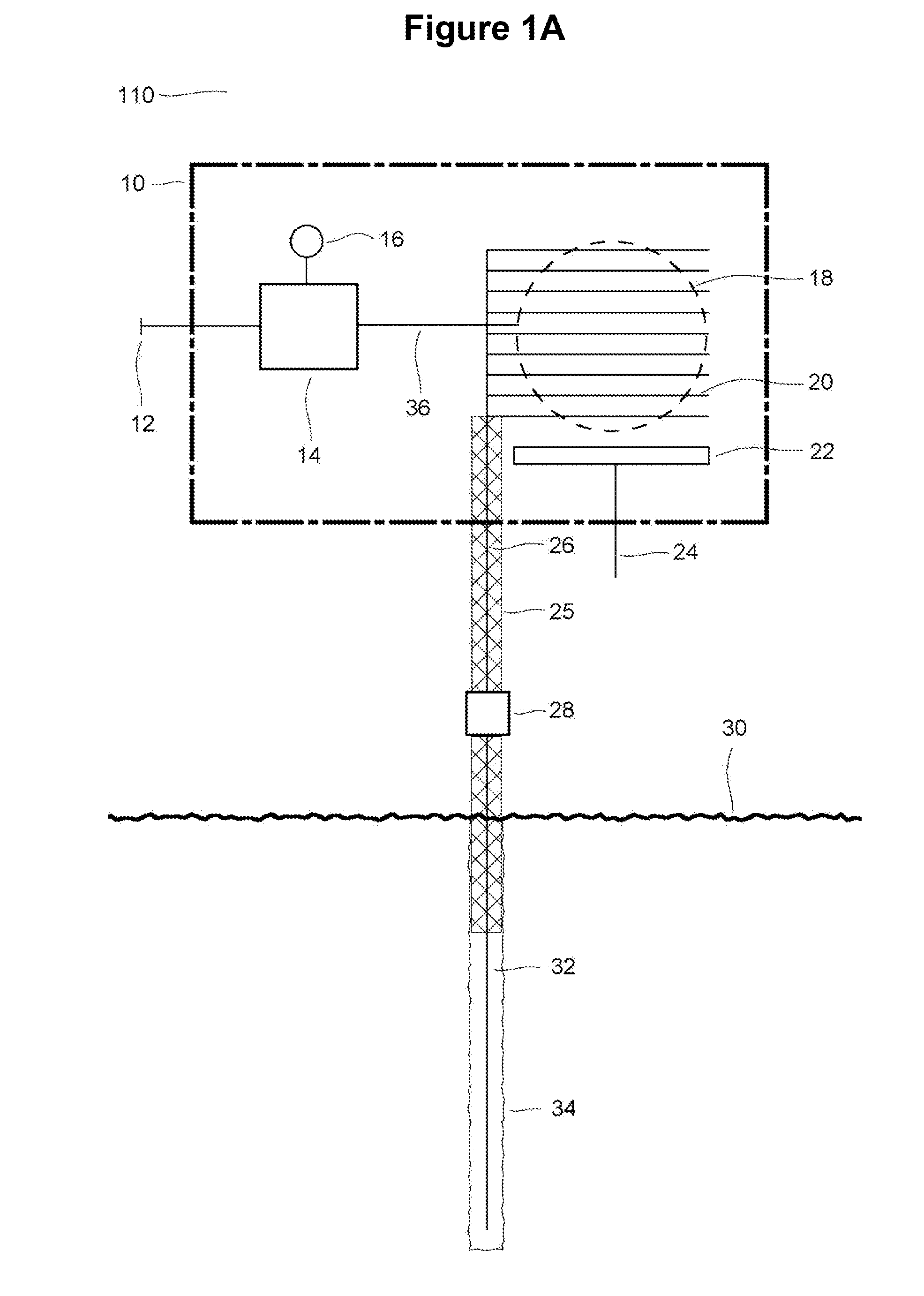
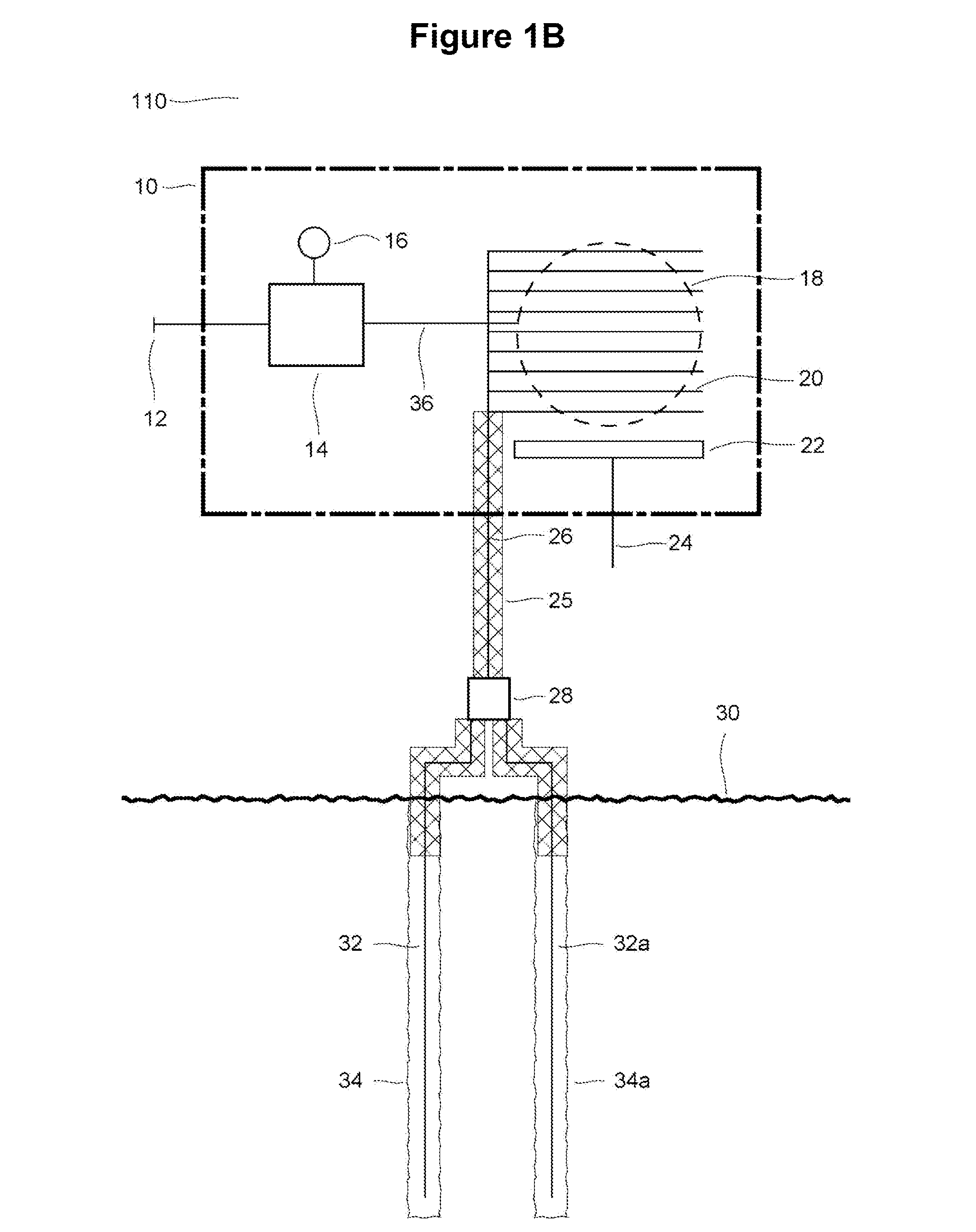
[0026] With reference to the drawings, new and improved cooling devices and systems for improved cooling embodying the principles and concepts of the present invention will be described. In particular, the devices and systems are operable in the conditions where an earth source temperature is lower than an above ground temperature associated with an interior space to be cooled. The earth source may alternatively be a ground source or a body of water effectively below ground level.

[0027] Recent advances in thermal superconducting materials can now be considered for use in novel energy transfer applications. For example, U.S. Pat. No. 6,132,823 and continuations thereof, discloses an example of a heat transfer medium with extremely high thermal conductivity, and is included herein by reference. Specifically the following disclosure indicates the orders of magnitude improvement in thermal conduction; “Experimentation has shown that a steel conduit 4 with medium 6 properly disposed th...


PUM


Abstract

A geothermal cooling device is couplable to a ground coil formed from a thermal superconductor material. The device includes a thermal superconductor heat exchange coil, and a thermostat controller and a blower. The device uses a high thermal transfer superconductor to efficiently move heat to the earth source for the purpose of cooling. The device operates by controlling the blower operation in response to the difference between a set point and a measured temperature. Optionally cooling device is enclosed in a housing mounted in standard structural spaces. Alternative simplified versions, without a thermostat, operate manually with a switch or power connection.

Description

FIELD OF THE INVENTION [0001] The present invention relates generally to geothermal cooling systems, and more particularly to a geothermal cooling device coupled with a superconducting heat transfer element for use as an air conditioner. BACKGROUND OF THE INVENTION [0002] Ground source heat pump systems, also known as geothermal or geoexchange systems, have been used for cooling and heating homes for more than half a century. In 1993, the Environmental Protection Agency evaluated all commercially available technologies and concluded that ground source heat pumps were the most energy efficient systems available to the consumer. [0003] Conventional ground source heat pump systems operate on a simple principle. In the cooling mode, heat from the building is collected at a heat exchanger and transferred to the heat pump, which concentrates the heat and transfers it to a ground source loop, which transfers the heat to the ground. In the heating mode, heat energy is absorbed from the grou...

Claims


Application Information

Patent Timeline
IPC IPC(8): F25D23/12F24F5/00F24F1/14F24F3/06F24F13/30F28F23/00
CPCF24F5/0046F24J3/086F28D15/0266Y02B10/40Y02E10/16Y02E60/142Y02E70/30F28D20/0052F24T10/40Y02E10/10Y02E60/14
Inventor MUELLER, LYNNGRAHAM, JOHN
Owner FREE ENERGY SOLUTIONS
Why Eureka
Try Eureka