Optical pickup device

a pickup device and optical technology, applied in the field of optical pickup devices, can solve the problems of the adjustment mechanism and the process of the axis adjustment, and achieve the effects of preventing the occurrence of coma aberration, reducing manufacturing costs, and high precision

Inactive Publication Date: 2008-03-06
FUNAI ELECTRIC CO LTD
View PDF6 Cites 1 Cited by
  • Summary
  • Abstract
  • Description
  • Claims
  • Application Information

AI Technical Summary

Benefits of technology

[0015] In the present invention, each of the electrodes of the liquid crystal device is a single electrode formed in a wide range in the substrate. Consequently, by applying a voltage across the electrodes, the refractive index of the whole electrode region in the liquid crystal device changes uniformly. Since the liquid crystal device is provided in front of the collimator lens when viewed from the light sources and a laser beam enters the liquid crystal device before the laser beam is converted to parallel rays by the collimator lens, by changing the refractive index of the liquid crystal device uniformly, the air conversion length between the light source and the collimator lens is changed. Since the degree of parallelization of light going out from the collimator lens is changed by the change in the air conversion length, spherical aberration in the objective lens can be corrected by controlling the degree of parallelization of outgoing light of the collimator lens by varying the refractive index of the liquid crystal device.
[0016] In the present invention, the liquid crystal device is provided in front of the collimator lens. Consequently, unlike the conventional case where the liquid crystal device is provided in front of the objective lens, it is unnecessary to adjust the axis of the objective lens and that of the liquid crystal device with high precision to prevent occurrence of coma aberration and, accordingly, a process for the adjustment of axis and an adjusting mechanism are unnecessary. As a result, the manufacturing cost can be decreased. In addition, it is unnecessary to assemble the liquid crystal device together with the objective lens into the movable actuator. Therefore, as compared with the conventional case where the liquid crystal device is mounted in the movable actuator, the movable actuator is lighter and the response (sensitivity) of the optical pickup is improved. Further, since the refractive index of the liquid crystal device is changed uniformly, the electrode formed in the substrate of the liquid crystal device can be a single electrode. Therefore, as compared with the conventional structure of providing the plurality of electrodes and controlling the refractive index individually, the structure of the electrode is simpler. Thus, the cost of the liquid crystal device can be reduced, and the control of the refractive index is simpler. Moreover, since wiring for supplying voltage to the electrode of one channel is sufficient, the number of wires is decreased, and the number of works and the space can be reduced.
[0017] Thus, the present invention can provide the optical pickup device in which a liquid crystal device is easily attached so that mass productivity is high, a movable actuator is light, excellent response can be obtained and, moreover, the liquid crystal device can be easily controlled.

Problems solved by technology

Consequently, unlike the conventional case where the liquid crystal device is provided in front of the objective lens, it is unnecessary to adjust the axis of the objective lens and that of the liquid crystal device with high precision to prevent occurrence of coma aberration and, accordingly, a process for the adjustment of axis and an adjusting mechanism are unnecessary.
In addition, it is unnecessary to assemble the liquid crystal device together with the objective lens into the movable actuator.

Method used


Image

  • Optical pickup device
  • Optical pickup device
  • Optical pickup device

Examples


Embodiment Construction

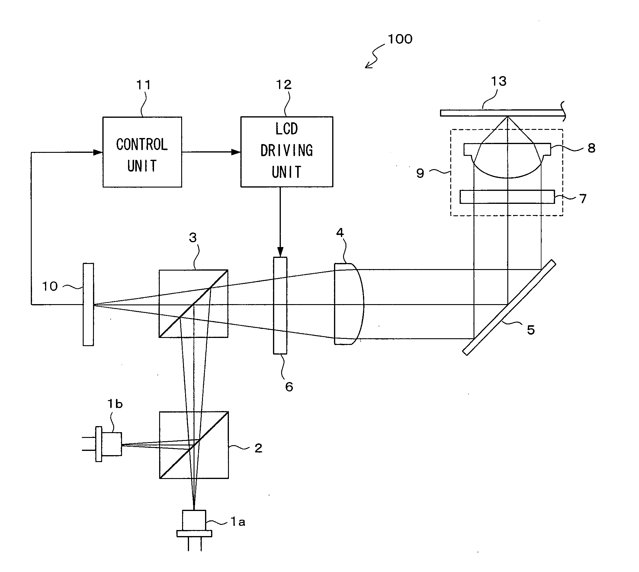
[0025]FIG. 1 is a schematic configuration diagram showing an optical system of an optical pickup device according to the embodiment of the present invention. A three-wavelength compatible optical pickup device 100 compatible with three kinds of discs of a CD, a DVD, and a BD (Blu-ray Disc) will be taken as an example.

[0026] In FIG. 1, reference numeral 1a denotes a light source for a CD and a DVD. The light source 1a includes two semiconductor lasers for emitting an infrared laser beam having a wavelength of 780 nm and a red laser beam having a wavelength of 650 nm. Reference numeral 1b denotes a light source for a BD. The light source 1b includes a semiconductor laser for emitting a blue laser beam having a wavelength of 410 nm. A beam splitter 2 transmits the laser beam from the light source 1a so that the laser beam travels straight, and reflects the laser beam from the light source 1b so that the optical path of the laser beam is changed by 90°. A beam splitter 3 reflects the l...


PUM

PropertyMeasurementUnit
wavelengthaaaaaaaaaa

Abstract

The present invention provides an optical pickup device in which a liquid crystal device is easily attached, mass productivity is high, a movable actuator is light, excellent response can be obtained and, moreover, the liquid crystal device can be easily controlled. In an optical pickup device in which laser beams emitted from light sources pass through a collimator lens and an objective lens and are condensed to a surface of an optical disc, a liquid crystal device for correcting spherical aberration of an outgoing light from the objective lens is provided in front of the collimator lens when viewed from the light sources. The liquid crystal device has a single electrode formed in a wide range in each of a pair of substrates facing each other while sandwiching liquid crystal. A predetermined voltage is applied to the electrode to uniformly change the refractive index of the whole electrode region in the liquid crystal device and make air conversion length between the light sources and the collimator lens variable, thereby changing the degree of parallelization of outgoing light from the collimator lens and correcting spherical aberration.

Description

BACKGROUND OF THE INVENTION [0001] 1. Field of the Invention [0002] The present invention relates to an optical pickup device used for reading information on an optical disc in a DVD recorder, a personal computer, or the like. [0003] 2. Description of the Prior Art [0004] Generally, in an optical pickup device used for a DVD recorder or the like, a laser beam emitted from a light source is converted by a collimator lens to parallel rays. The laser beam passed through the collimator lens is condensed by an objective lens onto the surface of an optical disc so as to form a light spot on the disc surface. In this case, when the light spot on the disc surface is blurred due to spherical aberration of the objective lens, the detection precision of the laser beam reflected by the disc surface deteriorates, and the adverse influence is exerted on the reproduction performance. [0005] One of methods for correcting the spherical aberration is adjustment of the lens position by making the coll...

Claims


Application Information

Patent Timeline
Patent Type & Authority Applications(United States)
IPC IPC(8): G01N21/55G11B7/126G11B7/135G11B7/1392
CPCG11B7/1369G11B2007/0006G11B7/13925
Inventor TANABE, NORITAKAKAMIOKA, YUICHI
Owner FUNAI ELECTRIC CO LTD
Why Eureka
Try Eureka