Guided-mode resonance sensors employing angular, spectral, modal, and polarization diversity for high-precision sensing in compact formats

a technology of angular, spectral, modal, and polarization diversity, applied in the direction of optical radiation measurement, instruments, spectrometry/spectrophotometry/monochromators, etc., can solve the problem that the change in refractive index and thickness cannot be resolved in one measurement at the same time, and the spectral sensitivity is very high, so as to improve the quality of the sensing operation and enhance the measurement precision. , the effect of improving the quality

Inactive Publication Date: 2008-03-13
MAGNUSSON ROBERT +1
View PDF98 Cites 28 Cited by
  • Summary
  • Abstract
  • Description
  • Claims
  • Application Information

AI Technical Summary

Benefits of technology

[0008]The present disclosure provides tag-free resonant sensors operating in reflection (that is, bandstop filter) or in transmission (that is, bandpass filter) wherein shaped angular spectra illuminate the GMR sensor element. These spectra simultaneously cover the incident angular ranges of interest with the received signal illuminating a linear detector array, or a CCD matrix, or other detectors, directly. On biomolecular attachment, or upon other variations of interest in the sensing region, these relatively narrow reflected or transmitted angular spectra alter their location on the detector matrix yielding a quantitative measurement of the molecular event of interest. Moreover, as the resonances arise as distinct TE and TM polarized responses, switching the input light polarization state can be applied to improve the quality of the sensing operation, or to measure additional parameters, by obtaining dual TE / TM resonance data. In addition, if desired, the input light can be spectrally tuned through a set of discrete wavelengths, thereby spatially shifting the locations of the measured spectra on the detectors providing possibilities of added enhancements of the precision of the measurement. Finally, sensor operation with multiple resonance peaks due to presence of multiple leaky waveguide modes can even further add to the measurement precision.
[0009]These operational modalities (angular, spectral, modal, and polarization) can be used in various combinations as needed. The sensors can be arranged into compact, high-density platforms requiring minimal reagent volumes. Therefore, as explained in this disclosure, this approach has numerous advantageous uses in practical sensor systems for high-precision measurement applications.

Problems solved by technology

While angular and spectral sensitivity is very high for these sensors, the resolution is limited by a broad resonant linewidth (˜50 nm) and signal to noise ratio of the sensor response.
Since only a single polarization (TM) can physically be used for detection, change in refractive index and thickness cannot simultaneously be resolved in one measurement.

Method used


Image

  • Guided-mode resonance sensors employing angular, spectral, modal, and polarization diversity for high-precision sensing in compact formats
  • Guided-mode resonance sensors employing angular, spectral, modal, and polarization diversity for high-precision sensing in compact formats
  • Guided-mode resonance sensors employing angular, spectral, modal, and polarization diversity for high-precision sensing in compact formats

Examples


Embodiment Construction

Background

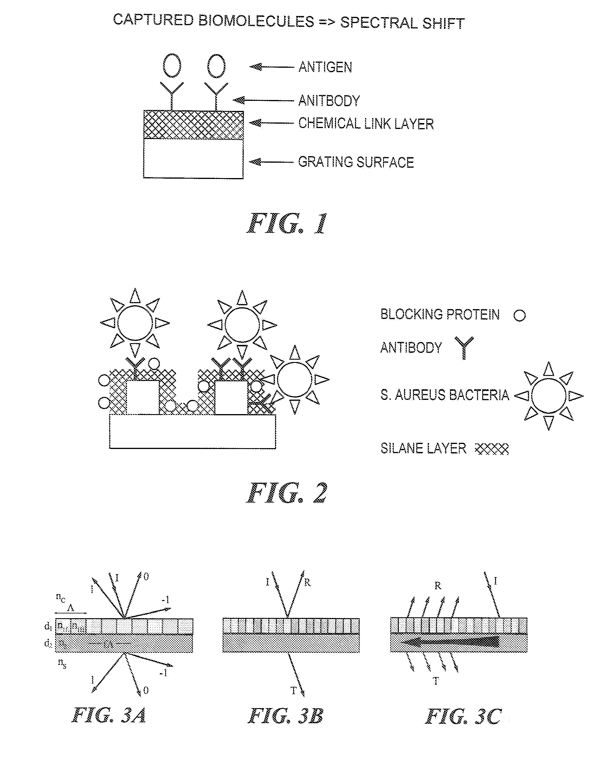
[0048]It has been suggested by the inventors that by changing the refractive index and / or thickness of a resonant waveguide grating, its resonance frequency can be changed, or tuned. The present inventors have discovered that this idea has applications for biosensors as the buildup of the attaching biolayer can be monitored in real time, without use of chemical tags, by following the corresponding resonance wavelength shift with a spectrometer. Thus, the association rate between the analyte and its designated receptor can be quantified; in fact, the characteristics of the entire binding cycle, involving association, disassociation, and regeneration can be registered. Similarly, small variations in the refractive indices of the surrounding media, or in any of the waveguide-grating layers, can be measured. A new class of highly sensitive bio- and chemical sensors has thus been enabled. This sensor technology is broadly applicable to medical diagnostics, drug development, ind...


PUM


Abstract

A guided mode resonance (GMR) sensor assembly and system are provided. The GMR sensor includes a waveguide structure configured for operation at or near one or more leaky modes, a receiver for input light from a source of light onto the waveguide structure to cause one or more leaky TE and TM resonant modes and a detector for changes in one or more of the phase, waveshape and / or magnitude of each of a TE resonance and a TM resonance to permit distinguishing between first and second physical states of said waveguide structure or its immediate environment.

Description

PRIORITY[0001]This application claims priority to provisional patent application Ser. No. 60 / 163,705, filed Nov. 5, 1999, the entire text of which is specifically incorporated by reference herein without disclaimer. This application also claims priority to provisional patent application Ser. No. 60 / 164,089, filed Nov. 6, 1999, the entire text of which is specifically incorporated by reference herein without disclaimer. This application also claims priority to provisional patent application Ser. No. 60 / 825,066, filed Sep. 8, 2006, the entire text of which is specifically incorporated by reference herein without disclaimer. This application also claims priority to U.S. patent application Ser. No. 09 / 707,435, filed Nov. 6, 2000, which claimed priority from provisional patent application Ser. Nos. 60 / 163,705 and 60 / 164,089, the entire text of which is specifically incorporated by reference herein without disclaimer.BACKGROUND OF THE DISCLOSURE[0002]1. Field of the Invention[0003]The pre...

Claims


Application Information

Patent Timeline
Patent Type & Authority Applications(United States)
IPC IPC(8): G01J3/30
CPCG01N21/253G01N2021/7776G01N21/7743G01N21/21G01N2021/7769
Inventor MAGNUSSON, ROBERTWAWRO, DEBRA D.
Owner MAGNUSSON ROBERT
Why Eureka
Try Eureka