High heat distortion resistant inorganic laminate

a technology of inorganic laminates and heat dissipation resistance, which is applied in the direction of natural mineral layered products, water-setting substance layered products, chemistry apparatuses and processes, etc. it can solve the problems of increased service temperature, limited flammability, smoke and gas generation, etc., and achieves high temperature resistance, favorable properties, and light weight

Inactive Publication Date: 2008-03-13
THE BF GOODRICH CO
View PDF48 Cites 93 Cited by
  • Summary
  • Abstract
  • Description
  • Claims
  • Application Information

AI Technical Summary

Benefits of technology

[0008] A heat distortion resistant laminate comprises at least one reinforcing core layer and at least one external metallosilicate containing layer desirably having a reinforcement therein such as a fiber. The core layer generally provides light weight and high temperature resistance and comprises an inorganic, high-temperature resistant composition containing various compounds such as refractory materials; ceramics; various oxides of aluminum, silicon, phosphorus, magnesium, titanium, or zirconium, or the like and can be in the form of a honeycomb structure, an undulating layer, etc. The laminate has favorable properties such as light weight, desirable impact resistance, high-temperature resistance and very low steepness index (distortion) values when thermally quenched.

Problems solved by technology

Although organic polymer composites exhibit excellent physical and mechanical properties, they are limited with regard to flammability, smoke and gas generation and elevated service temperatures.
The substitution of hydrogen atoms with halogen atoms (such as for example, chlorine) in hydrocarbons and hydrocarbon polymers can significantly reduce flammability and smoke / gas generation but will degrade at temperatures greater than 250° C. and eventually incinerate at temperatures greater than 450° C. Organic thermoplastic polymers also deform at relatively low temperatures (about 100° C.-300° C.) and organic polymers designed for higher service temperatures are generally prohibitive in material and processing costs.

Method used


Image

  • High heat distortion resistant inorganic laminate
  • High heat distortion resistant inorganic laminate
  • High heat distortion resistant inorganic laminate

Examples


examples

[0151] The following examples serve to illustrate and describe a preferred embodiment of the present invention but not to limit the same in that other embodiments can be utilized.

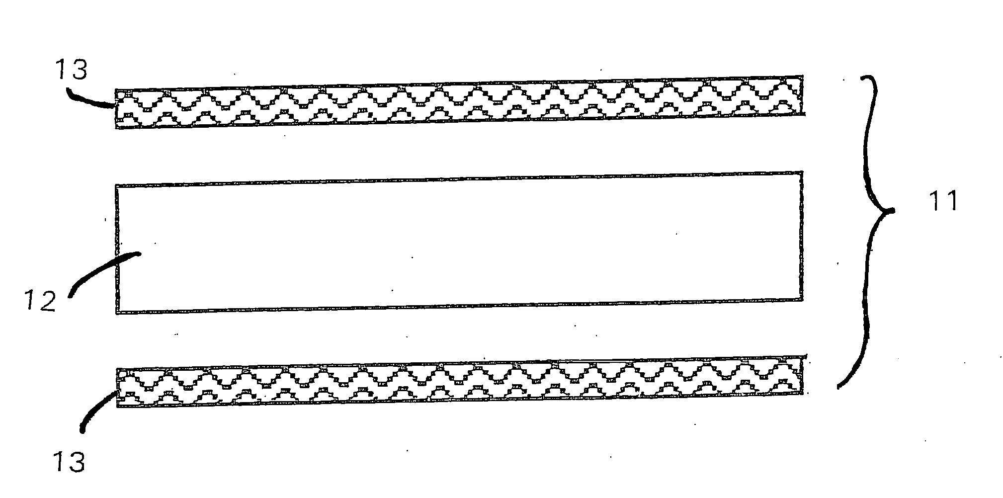
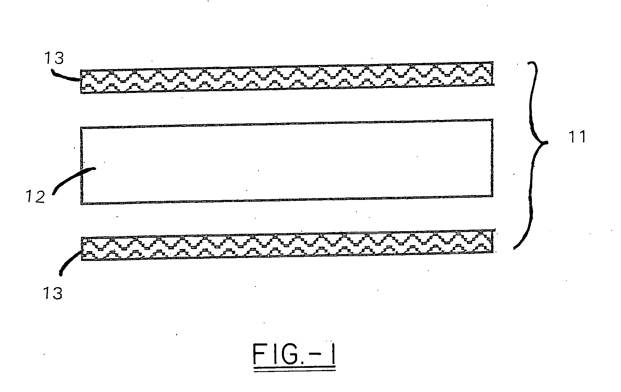
[0152] A laminate in the form of a panel was fabricated for testing with regard to thermal shock resistance as quantified by a quench steepness index value. The panel contained face sheets on both top and bottom with an insulative core. This panel was made by first curing the bottom face sheet; then bonding the core material and curing the top face sheet in a separate step. The process is discussed below along with the test results.

[0153] The bottom and top layers of the panel were fabricated using an aqueous inorganic resin slurry comprising 70 wt. % potassium silicate, 1.8 wt. % potassium dihydrogen phosphate, 9.7 wt. % clay, 2.04 wt. % boric acid, 1.85 wt. % magnesium oxide, and 3.6 wt. % of a reactive acidic glass such as borophosphosilicate. The slurry was impregnated using squeeze rolls into a silic...


PUM

PropertyMeasurementUnit
thermal resistanceaaaaaaaaaa
temperatureaaaaaaaaaa

Abstract

A light-weight, heat distortion resistant laminate includes at least one layer of an alkali silicate resin composition derived from an alkali silicate and/or alkali silicate precursor, at least one oxoanionic compound or a reactive acidic glass; and water; and at least one reinforcing core layer comprising an inorganic high-temperature resistant composition. The laminate has a very low quench steepness index value upon rapid quenching as with ambient temperature water.

Description

CROSS REFERENCE TO RELATED APPLICATIONS [0001] This application is a continuation-in-part application of U.S. patent application Ser. No. 10 / 858,624, filed Jun. 2, 2004 entitled “Multi-Layer Fire-Resistant Systems”, which is a continuation-in-part of U.S. Provisional Patent Application 60 / 476,671, filed Jun. 6, 2003, entitled “Fire Resistant Barrier”. U.S. patent application Ser. No. 10 / 858,624, filed Jun. 2, 2004, entitled “Multi-Layer Fire-Barrier Systems”, is a continuation-in-part of U.S. patent application Ser. No. 10 / 777,885, filed Feb. 12, 2004, entitled “Inorganic Matrix Compositions, Composites incorporating the Matrix, and Process of Making the Same” which in turn is a continuation-in-part of U.S. patent application Ser. No. 09 / 871,765, filed Jun. 1, 2001, which in turn claims the benefit of U.S. Provisional Patent Application 60 / 233,952, filed Sep. 20, 2000, entitled “Inorganic Matrix Compositions, Composites and Process of Making the Same”. U.S. patent application Ser. N...

Claims


Application Information

Patent Timeline
Patent Type & Authority Applications(United States)
IPC IPC(8): B32B17/06B32B9/04
CPCB32B1/08B32B5/18B32B5/26C09K21/02B32B15/18B32B17/02B32B15/02
Inventor ROBINSON, JOHN W.CARTWRIGHT, CRAIG L.MAZANY, ANTHONY M.
Owner THE BF GOODRICH CO
Why Eureka
Try Eureka