Method for Solid-Phase-Micro Extraction and Apparatus Therefor

a solid-phase micro and extraction method technology, applied in the direction of separation process, liquid displacement, laboratory glassware, etc., can solve the problems of inability to apply the method to an analysis of a thermally decomposable component, reduced contact efficiency, and longer time required for equilibration of analyte with liquid phase, so as to achieve the effect of reducing the time required for running one analysis and increasing the flow ra

Inactive Publication Date: 2008-03-13
GL SCI
View PDF6 Cites 61 Cited by
  • Summary
  • Abstract
  • Description
  • Claims
  • Application Information

AI Technical Summary

Benefits of technology

[0007]According to the present invention, a flow rate can be increased under a low pressure condition by improving a particle-packed type of column which has been commonly used and which requires a high pressure for passing a liquid (or a gas) through the column, and a time required for running one analysis can be reduced by improving the SPME pre-treatment which requires one hour or more for reaching an equilibrium state in the case of certain samples and then a great deal of time is required for running one analysis. Therefore, the first aspect of the present invention, which is a method for performing a solid-phase extraction of a component present in a sample and which utilizes a syringe having a cylinder and a plunger slidable within the cylinder, a tip of the syringe being provided with a needle and the needle being provided with a porous body having an integral structure of open cell structures (hereinafter, referred to as a so-called monolithic structure) along at least an appropriate length of the needle and across an overall diameter of the needle, is characterized by comprising the steps of inserting the needle into the sample, passing the sample through the needle to retaining an analyte within the porous body, and desorbing the retained analyte from the porous body.

Problems solved by technology

However, there is a problem that the time required for equilibrating the analyte with the liquid phase becomes longer as the film thickness is increased.
In addition, this method cannot be applied to an analysis of a thermally decomposable component because the sample is thermally desorbed when the sample is introduced into the analytical system.
However, as the inner diameter increases, a contact efficiency is reduced due to an extended diffusion time.
Further, in a method which uses a column being packed with a filler, there are some problems as follows: (1) a flow rate depends on the packing state, so that analytical values will vary; and (2) resistance to a stream of the fluid becomes larger and the flow rate per unit time is decreased, so that the analytical time becomes longer.
In this method, thermal desorption is also carried out at an existing GC injection port, so that broadening of a peak width cannot be avoided.

Method used


Image

  • Method for Solid-Phase-Micro Extraction and Apparatus Therefor
  • Method for Solid-Phase-Micro Extraction and Apparatus Therefor
  • Method for Solid-Phase-Micro Extraction and Apparatus Therefor

Examples


example 1

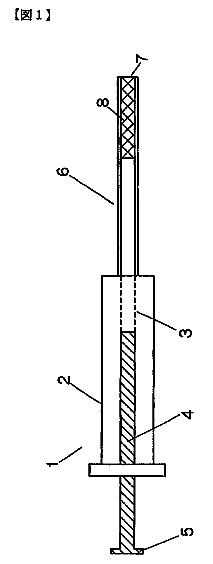
[0049]An example of the present invention will be described with reference to FIG. 1.

[0050]A syringe 1 is comprised of a cylinder 2 and a plunger 4 which is slidably provided within an inner cylinder 3 of the cylinder 2. A head portion of the plunger 4 is provided with a handle 5. A tip of the cylinder 2 is provided with a needle 6. An inside of the needle 6, over a length of 4 mm thereof, is packed with a cylindrical porous body 7 which is made of a porous glass and through which pores 8, 8, . . . are formed along an axial direction, the average pore size being 10 μm.

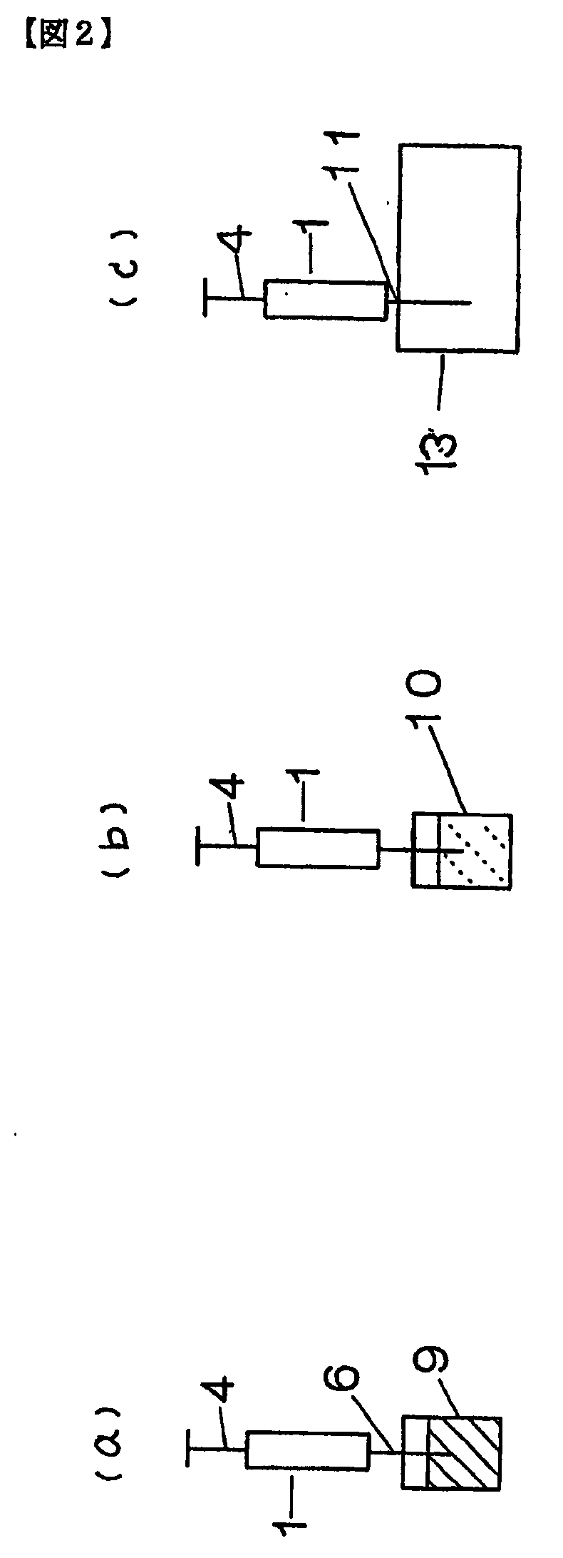
[0051]A procedure for manually actuating the syringe 1 will be described with reference to FIG. 2. Methanol or the like is firstly passed through the needle 6 for conditioning a state of the porous body. The needle 6 is inserted through a sample bottle 9, then the sample is sucked up by actuating the plunger 4, FIG. 2(a). This suction allows the sample to pass through the porous glass of the porous body 7 when the samp...

example 2

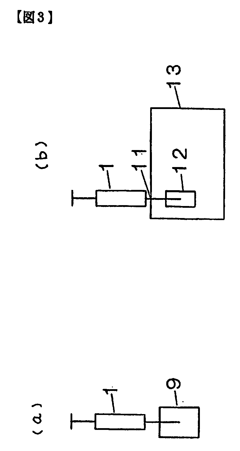
[0053]A next example of the present invention will be described with reference to FIG. 3.

[0054]In contrast to Example 1 in which the analyte is eluted by the solvent, this example uses heat instead of the solvent in order to desorb the sample.

[0055]Specifically, the sample is sucked by actuating the plunger as in the case of Example 1, FIG. 3(a). Then, a heating mechanism 12 which is ordinary provided at the injection port 11 of the gas chromatograph is utilized. The needle 6 containing the sample which is diffused and retained in the pores 8, 8, . . . of the porous body as in the case of the above-described Example 1 is inserted into the injection port 11. Gas is supplied from a supplying port which is provided at an upper portion or a middle portion of the syringe 1 and the needle 6 is heated by the heating mechanism 12, then the sample undergoes physical desorption and is introduced into the gas chromatograph, FIG. 3(b).

example 3

[0056]Another example of the present invention will be described with reference to FIG. 4 and FIG. 5.

[0057]In this example, the needle 6 is constructed to be attachable / detachable with respect to the syringe 1. In this construction, the needle 6 is made short, and the tip of the needle 6 is provided with a capillary 62 having an insertion part 61 for the needle 6. This capillary 62 is constructed to be attachable / detachable with respect to the needle 6 with the above described cylindrical porous body 7 formed within the capillary 62 (FIG. 4). In this case, a tapered sample tip which has been conventionally used for chemical reactions or immunoreactions can be used as the capillary 62 with the porous body formed therein. In addition, as another example, a holding part 63 for holding the needle 6 is formed at a tip of the syringe 1 and also the corresponding insertion part 64 is provided at the needle 6 (FIG. 5).

[0058]Further, it is of course possible to use a tapered sample tip 65 ha...


PUM

PropertyMeasurementUnit
thicknessaaaaaaaaaa
pore sizeaaaaaaaaaa
diameteraaaaaaaaaa

Abstract

The present invention is directed to a system for pre-treatment of a sample to be introduced in a chromatograph, and a method for performing solid-phase extraction of a component present in a sample. The system uses a syringe having a needle being provided with a porous body having a monolithic structure along at least an appropriate length of the needle and across an overall diameter of the needle. The method includes the steps of inserting the needle into the sample, passing the sample through the needle to retain an analyte within the porous body, and desorbtion of the retained analyte from the porous body.

Description

TECHNICAL FIELD[0001]The present invention relates to a method and apparatus for solid-phase-micro extraction, and particularly relates to a treating method and apparatus effective for a pre-treatment of a sample which is introduced to a chromatograph.BACKGROUND ART[0002]In a chromatographic analysis, it has been said that the time and effort required for the so-called pre-treatment, including sampling, extraction of an analyte, and sample preparation such as concentration represents 80% of the analytical work. Solid-Phase-Micro extraction (SPME) developed by Pawliszyn in 1990 is a method for pre-treating a sample, where such works and introduction into the chromatograph can be simply performed. In the SPME method, a fiber whose surface is coated with a liquid phase is exposed to a headspace or a solution of the sample in order to perform extraction, and an analyte extracted into the fiber liquid phase is thermally desorbed at a injection port during GC and is introduced to the GC (...

Claims


Application Information

Patent Timeline
Patent Type & Authority Applications(United States)
IPC IPC(8): G01N1/18B01D15/00G01N30/00B01J20/28B01L3/02G01N1/34G01N1/40G01N30/18
CPCB01D15/00Y10T436/255B01J20/28054B01J20/28092B01J2220/64B01L3/022B01L3/0275B01L2200/0631G01N1/40G01N1/405G01N30/06G01N30/18G01N2030/009G01N2030/062B01D15/08B01J20/28042
Inventor HIRAMATSU, YUKAYAMASAKI, KAZUHIKOFURUNO, MASAHIRO
Owner GL SCI
Why Eureka
Try Eureka