Holographic Sensor

a holographic sensor and sensor technology, applied in the field of holographic sensors, can solve the problems of not being able to absorb enough light through the skin, holograms do not generally reflect light of sufficient intensity, etc., and achieve the effect of increasing the brightness and sensitivity of holographic sensors and reducing the level of unwanted effects

Inactive Publication Date: 2008-03-20
CAMBRIDGE ENTERPRISE LTD
View PDF10 Cites 3 Cited by
  • Summary
  • Abstract
  • Description
  • Claims
  • Application Information

AI Technical Summary

Benefits of technology

[0008] The present invention is based on a realisation that the brightness and sensitivity of holographic sensors can be increased by reducing the levels of unwanted (“background”) silver binding.

Problems solved by technology

However, the holograms do not generally reflect light of sufficient intensity to penetrate through the skin and be detected.
This is mainly because of problems of light scatter.
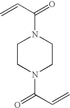
They found that any cross-linker with free amides such a methylenebisacrylamide (MBA) tended to cause a lot of background staining.

Method used


Image

  • Holographic Sensor

Examples


example 1

[0029] A support medium was formed by copolymerising 12 mol % 3-aminophenylboronic acid, 86.5 mol % acrylamide, and 1.5 mol % BAP as a cross-linker. A similar medium was then formed, using 1.5 mol % MBA as the cross-linker. Silver halide was then immobilised within each medium and a hologram recorded, using 2 pulses of laser light. Another medium was formed by the “silverless double polymerisation” of 12 mol % 3-aminophenylboronic acid and acrylamide, using 1.5 mol % MBA as the cross-linker. Again, a hologram was recorded in the medium.

[0030] The hologram of the sensor of the invention was considerably (of the order of 10-100 times) brighter than that the conventional sensors, even though only 2 pulses of laser light were used in its construction. Indeed, the hologram of the invention was so bright that it could even be viewed under a strip light. The responses of the various sensors were also compared, and were shown to be virtually identical. The diffraction peak of the sensor of...

example 2

[0031] A support medium was formed by copolymerising 5 mol % acrylic acid, 90 mol % of a 2:1 ratio of acrylamide:methacrylamide, and 5 mol % BAP as a cross-linker. Silver halide was then immobilised within the medium and a hologram was recorded. The sensor exhibited similar characteristics to the sensor of Example 1.


PUM

PropertyMeasurementUnit
physical propertyaaaaaaaaaa
temperatureaaaaaaaaaa
magnetismaaaaaaaaaa

Abstract

The invention relates to a sensor comprising a medium and, disposed therein, a hologram, wherein an optical characteristic of the medium changes as a result of a variation in a physical property of the medium, wherein the fringes of the hologram are formed by silver grains and wherein the medium comprises a material which does not bind silver. The brightness and sensitivity of such holographic sensors is increased as a result of reduction in the levels of unwanted (“background”) silver binding.

Description

FIELD OF THE INVENTION [0001] This invention relates to a holographic sensor. BACKGROUND TO THE INVENTION [0002] WO-A-95 / 26499 describes a holographic sensor. The sensor comprises a holographic support medium and, disposed throughout its volume, a hologram. The support medium interacts with an analyte, resulting in a variation of a physical property of the medium. This variation induces a change in an optical characteristic of the holographic element, such as its polarisability, reflectance, refractance or absorbance. If any change occurs whilst the hologram is being replayed (e.g. using incident broad band, non-ionising electromagnetic radiation), then a colour change, for example, may be observed using an optical detector. The optical detector may be a spectrometer or simply the human eye. [0003] WO-A-99 / 63408 describes an alternative method of producing a holographic sensor. A sequential treatment technique is used, wherein the polymer film is made first and sensitive silver hali...

Claims


Application Information

Patent Timeline
Patent Type & Authority Applications(United States)
IPC IPC(8): G03H1/02A61B5/00G01N21/47G01N21/77G03C1/00G03H1/18
CPCA61B5/14532A61B5/14546G01N21/4788G01N21/77G03H2260/16G03H1/0248G03H1/18G03H2001/0033G03C1/00
Inventor KABILAN, SATYAMOORTHYMARSHALL, ALEXANDER JAMES
Owner CAMBRIDGE ENTERPRISE LTD
Why Eureka
Try Eureka