Device for preparing microscopy samples

a microscopy and sample technology, applied in the field of microscopy sample preparation devices, can solve the problems of high labor intensity, difficult sample preparation, and inability to meet the requirements of the sample,

Active Publication Date: 2008-03-20
MICROSCOPY INNOVATIONS
View PDF2 Cites 25 Cited by
  • Summary
  • Abstract
  • Description
  • Claims
  • Application Information

AI Technical Summary

Problems solved by technology

Such images are capable of resolution down to approximately 0.1 nm, although this is usually not quite possible with biological materials.
However, the resolution of the SEM is typically not as fine as that of the TEM, yet high resolution versions are capable of molecular level resolution of approximately 5 nm.
Because of the delicate nature of microscopy samples and the resolution and power of LM, SEM and TEM analysis, sample preparation requires highly skilled and delicate manipulation.
Thus, methods and devices for their preparation have been devised that are either highly cumbersome and / or inadequate for their needs.
As illustrated by McCormick, inside the container and the cassette are large amounts of dead space resulting in the need for large volumes of fixation media, rinses, and other solutions in order to adequately process the sample.
Since many of the chemicals used are noxious and some are expensive to purchase or dispose of, large dead-space volumes are not desirable.
In addition, such cassettes are not intended for the preparation and handling of the circa 1 mm specimens typical in biological TEM and many clinical histopathology or biopsy specimens and hence such small specimens can readily become lost or misplaced.
As can be seen in the Dudek figures, the container has a large volume of dead space in which the sample can be lost or damaged.
Further, the sample can not be visually inspected nor can the sample be sectioned or stored in the container.
As with other, similar devices, the cassette disclosed by Williamson includes a large volume of dead space, and provides little ability to visually inspect the samples within.
Further, the cassettes taught by Williamson are not amendable to simultaneous use with other cassettes thus limiting their ability for high-throughput use.
In addition, as taught by Williamson et al., the cassettes are complicated devices having relatively high costs and not allowing for sectioning of the sample held within.

Method used


Image

  • Device for preparing microscopy samples
  • Device for preparing microscopy samples
  • Device for preparing microscopy samples

Examples


example 1

Grid Holding Micropipette Device and Sample Holding Micropipette Device

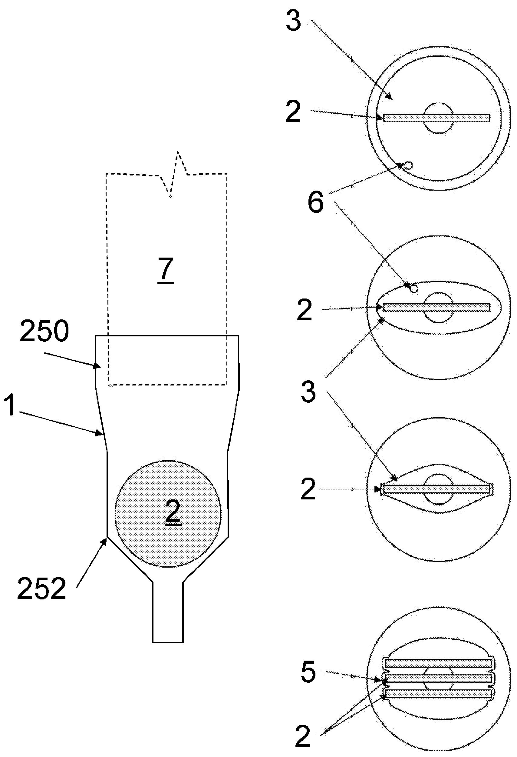
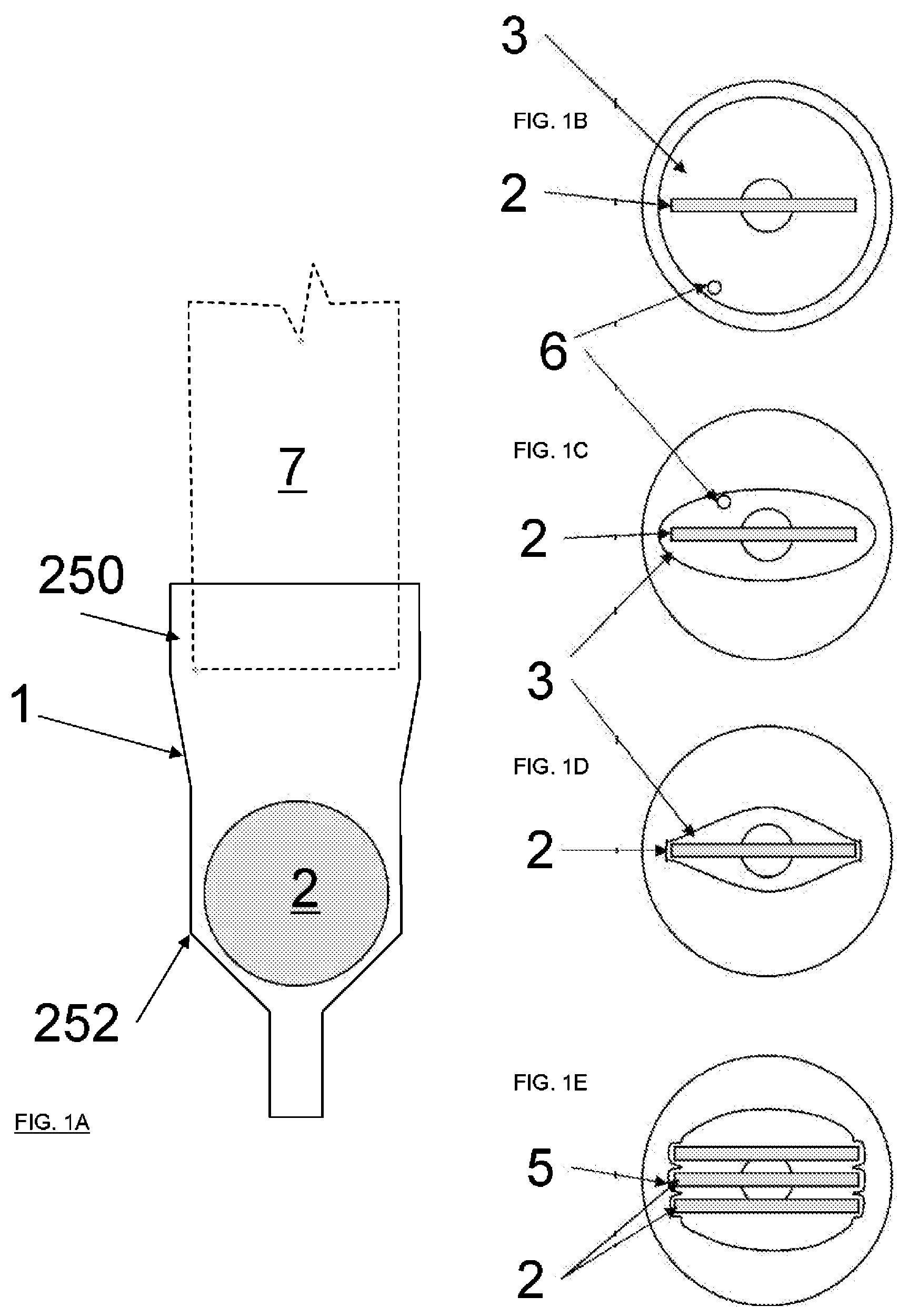
[0063]One embodiment of the invention is shown in FIGS. 1A-1E. As shown in FIG. 1A a reservoir such as a tapered tube-shaped holder 1 accepts an individual TEM grid 2 (or similar study object) within its lumen. Each grid 2 is held at its periphery by the taper or size of the tube, and / or by small protrusions within the tube so that the grid 2 is held by its edges such that the study objects on the grid face are protected from damaging contact with the tube wall. A number of profiles can be used to hold the grid 2 and prevent contact of the grid faces (flat aspects) with the sides of the tube. Lumens 3 that are broad or open as shown in FIG. 1B, provide for improved flow as may be desired with higher viscosity reagents or where rapid fluid exchange is desired, while lumens 3 having a more narrow shape reduce the volume required for staining or other treatments and / or more securely prevent grid motion as shown in F...

example 2

Preparation of SEM and Similar Specimens

[0073]An additional embodiment of the invention is shown in FIGS. 7A-7D. This embodiment is an SHMP 31 in which the screen or filter 40 is comprised of a mechanically robust support produced from an electrically conductive material (such as a suitable metal), or from a material that can be treated to provide electrical conductivity. The screen or filter 40 can be readily removed from the SHMP 31 and is then self-supporting. The screen or filter element 40 is conductive to facilitate use as a specimen support for SEM, but may also be used for other applications such as optical microscopy and atomic force microscopy where conductivity is not required. The pore size of the filter or screen 40 is selected to entrap the study objects as shown in FIG. 7B. As shown in FIG. 7A, a solution (or a suspension or a powder) of small study objects 41 are placed in the SHMP 31 and are then concentrated upon the conductive filter support 40 by filtration resul...

example 3

Positive Identification

[0075]It is difficult to mark or specifically identify individual microscope specimens due to their small size. Any identification marking or device would likely be too small to be useful as it would generally not be visible or otherwise identifiable without magnification, such as with a dissection microscope. Moreover, such marking cannot be conveniently done on a grid by a user, at least not without special equipment, nor may a tissue specimen or non-biological specimen be readily marked as most specimens are no more than a few millimeters in size. Current methods for identification during preparation or in storage depend upon the location of the specimen for its identification, such as via a numbered location in a grid box or labeled vial. Since grids are the end stage of TEM specimen preparation and as a single specimen may be sectioned and mounted on dozens of grids, and as such processing may have entailed many days of labor, the logistics of grid identi...


PUM


Abstract

A device, method and system for preparing and storing samples for microscopic analysis is disclosed. The device provides a reservoir that can be attached to a displacement pipette thereby filling the reservoir with reagents desired for preparing the samples for microscopic analysis. In some embodiments, the specimen may be contained on a transmission electron microscope (TEM) grid. In other embodiments, the sample may be a light microscope (LM) specimen or a scanning electron microscope (SEM) specimen. In yet another embodiment, the invention provides a method of preparing samples for microscopic examination including a device for preparing TEM grids with, a device for preparing TEM, SEM or LM specimens with and a device for storing both grids and specimens in. In yet another embodiment, the invention provides a system for tracking the preparation, analysis and histological evaluation of multiple samples while also providing for their long term storage.

Description

CROSS-REFERENCE TO RELATED APPLICATION[0001]This application is a continuation of U.S. application Ser. No. 11 / 752,239 filed May 22, 2007 and international application PCT / US07 / 69489 also filed May 22, 2007 both claiming priority to U.S. provisional application 60 / 747,928 filed on May 22, 2006, all of which are incorporated herein by reference in their entirety, for all purposes.FIELD OF THE INVENTION[0002]This invention is generally directed to a device used to handle and prepare specimens for analysis with light and electron microscopes including especially transmission electron microscopes (TEM), scanning electron microscopes (SEM) and light microscopes (LM).BACKGROUND OF THE INVENTION[0003]Light microscopes, transmission electron microscopes, scanning electron microscopes and other instruments are extensively used to understand the ultrastructure of a wide variety of synthetic and biological materials in numerous areas of science and technology. For example, light microscopy sam...

Claims


Application Information

Patent Timeline
Patent Type & Authority Applications(United States)
IPC IPC(8): G02B21/00
CPCB01L3/0275B01L3/502B01L2300/042B01L2300/0609B01L2300/0681G01N1/31H01J2237/201G01N2035/0427G01N2035/1048G02B21/34H01J2237/20H01J2237/2007G01N1/36
Inventor GOODMAN, STEVEN L.
Owner MICROSCOPY INNOVATIONS
Why Eureka
Try Eureka