
System and method for performance monitoring and reconfiguring computer system with hardware monitor

Inactive Publication Date: 2008-03-20
HITACHI LTD
View PDF2 Cites 109 Cited by
  • Summary
  • Abstract
  • Description
  • Claims
  • Application Information

AI Technical Summary

Benefits of technology

[0014]Servers and other similar computers often use a multiprocessor in which multiple CPUs are packaged. Computers with a small number of CPUs are short in memory latency, but in most cases employ a cluster system which puts in multiple servers to improve the performance, because the performance of such computers cannot be brought to a sufficient level with a multi-process or multi-thread application program, a typical example of which is the Online Transaction Processing (OLTP) system. On the other hand, computers with many CPUs can improve their performance scalably in proportion to the load by employing a multi-process application program, while their hardware, which is complicate due to the necessity to maintain cache memory coherency among those many CPUs, tends to prolong the memory latency. This sometimes makes the performance of small-scale servers with a few CPUs higher than that of large-scale servers when application programs employed have the same process or the same thread count. There is a problem in that determining which type of computer to use, large-scale or small-scale, requires an evaluation process that takes a lot of steps including a scalability evaluation in which an actual service application program or a standard benchmark program is put into operation.
[0016]A second object of this invention is to avoid applying an additional load for evaluation to a measurement target system by preventing software that collects performance information of a computer such as a server from taking a CPU time or other resources that are allocated to a measurement target application program while collecting the performance information.
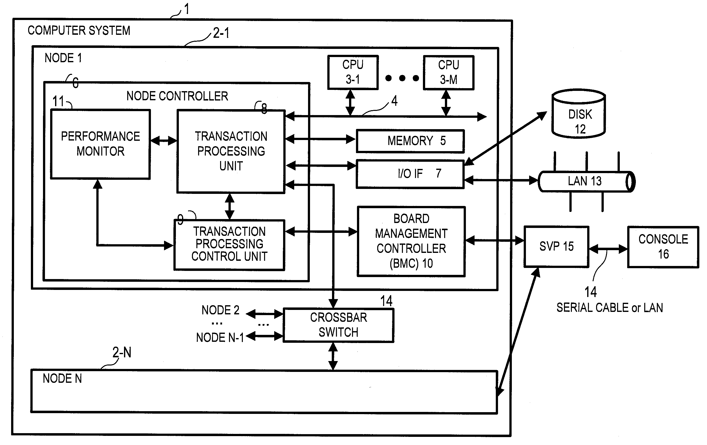
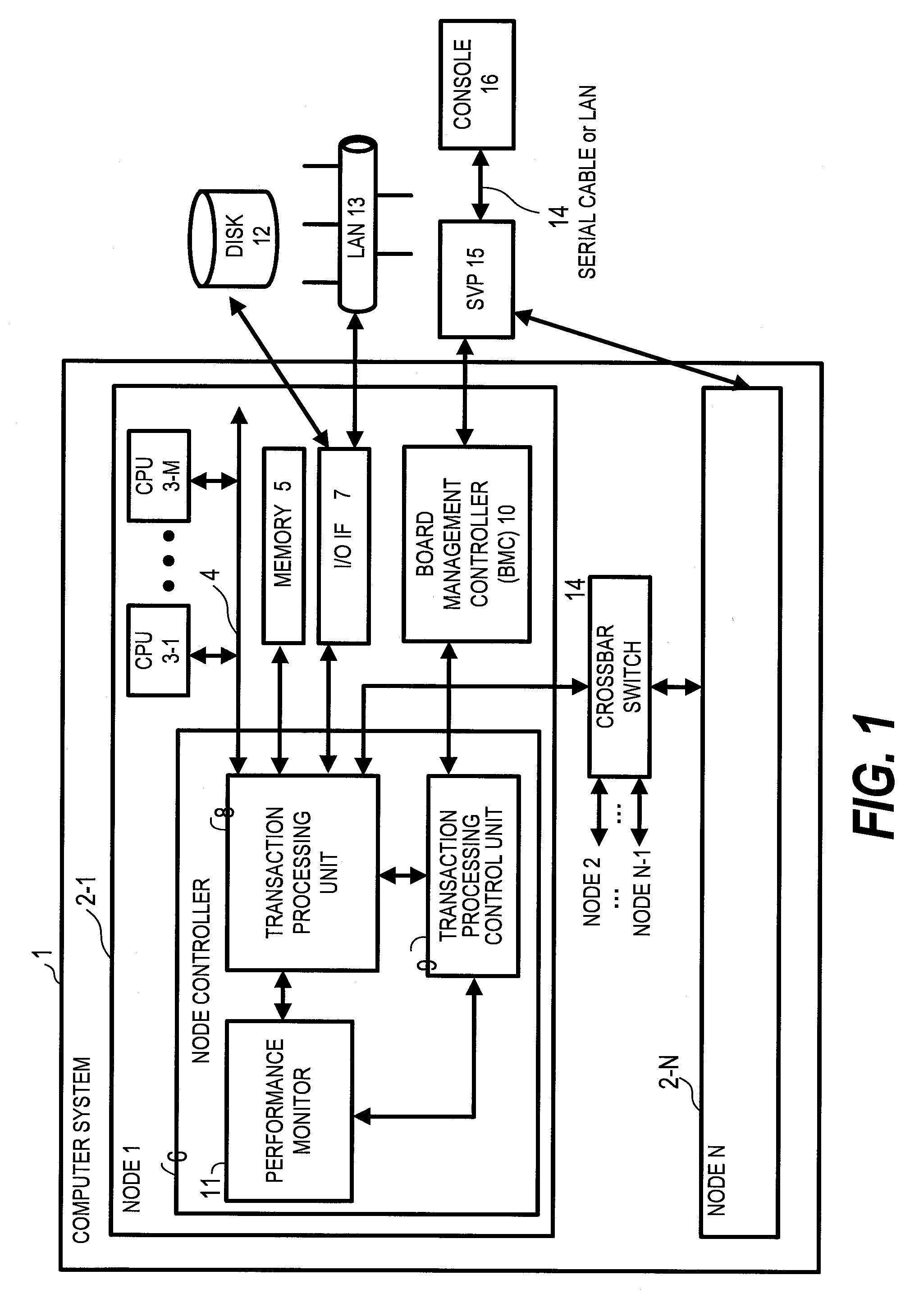
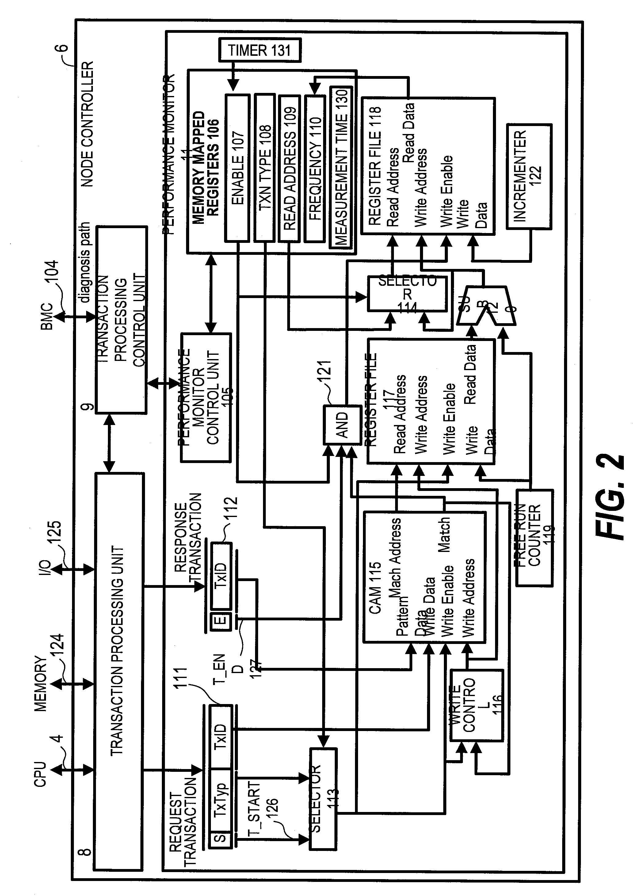
[0020]According to this invention, a controller placed between a memory and a CPU can measure the memory latency (response time) in association with the frequency of memory access requests, and a performance measurement can be carried out without applying a load for the performance measurement to the CPU. From the result of the measurement, a judgment can be made quickly about whether or not it is the memory or a chipset (the controller) that is causing a performance bottleneck in the CPU having an unchangeable internal configuration or in an application program that does not allow coding optimization.

Problems solved by technology

However, methods that use the performance monitor of the OS as those described above have a problem in that whether hardware is causing a performance bottleneck cannot be observed directly.
This solution is applicable only to compilers and CPUs, and cannot be applied to chipsets and other components of a server.
Furthermore, identification of a performance bottleneck location through coding optimization in the manner described above is generally difficult in a system where an application program distributed or purchased as executable binary code is run and, accordingly, tuning on the code level is impossible.
Computers with a small number of CPUs are short in memory latency, but in most cases employ a cluster system which puts in multiple servers to improve the performance, because the performance of such computers cannot be brought to a sufficient level with a multi-process or multi-thread application program, a typical example of which is the Online Transaction Processing (OLTP) system.
On the other hand, computers with many CPUs can improve their performance scalably in proportion to the load by employing a multi-process application program, while their hardware, which is complicate due to the necessity to maintain cache memory coherency among those many CPUs, tends to prolong the memory latency.
There is a problem in that determining which type of computer to use, large-scale or small-scale, requires an evaluation process that takes a lot of steps including a scalability evaluation in which an actual service application program or a standard benchmark program is put into operation.

Method used


Image

  • System and method for performance monitoring and reconfiguring computer system with hardware monitor
  • System and method for performance monitoring and reconfiguring computer system with hardware monitor
  • System and method for performance monitoring and reconfiguring computer system with hardware monitor

Examples


second embodiment

[0193]FIG. 21 shows a second embodiment in which the nodes 2-1 to 2-N of the computer system 1 of the first embodiment are replaced by blade servers 50-1 to 50-N, and a node controller 56 provided in each of the blade servers 50-1 to 50-N measures the performance. The rest of the configuration of the computer system in the second embodiment is the same as in the first embodiment.

[0194]The computer system of the first embodiment is composed of many nodes, and is partitioned physically. Described here is a contrasting example in which a small-scale computer system constitutes the base of the configuration.

[0195]FIG. 21 is a block diagram showing an example of a blade server that is equipped with a hardware monitor of this invention.

[0196]A computer system 1A has multiple blade servers 50-1, 50-2, . . . , 50-N (N is an integer equal to or larger than 1), an I / O board (or I / O blade) 60, and a backplane board 66, which interconnects the blade servers 50-1 to 50-N. The computer system 1A ...

third embodiment

[0239]FIG. 23 shows a third embodiment in which the degree of freedom in the latency measurement performed by the performance monitor 11 shown in FIG. 2 is increased by setting the range and interval of measured latencies arbitrarily.

[0240]Adding a circuit shown in FIG. 23 to the performance monitor 11 described in the first embodiment with reference to FIG. 2 makes it possible to set the range and interval of measured latencies and enhance the degree of freedom in the latency measurement. FIG. 23 shows only a part of the performance monitor 11 where the register file 117, the register file 118, and the components in between are located. The rest of the configuration shown in FIG. 23 is the same as the one described in the first embodiment with reference to FIG. 2. Also, components common to FIG. 2 which illustrates the first embodiment are denoted by the same reference symbols.

[0241](1) Circuit Outline

[0242]The outline of the circuit shown in FIG. 23 will be described. Read data of...


PUM


Abstract

A judgment is made quickly about whether or not it is a memory or a chipset that is causing a performance bottleneck in an application program. A computer system of this invention includes at least one CPU, a controller that connects the CPU to a memory and to an I / O interface, in which the controller includes a response time measuring unit, which receives a request to access the memory and measures a response time taken to respond to the memory access request, a frequency counting unit, which measures an issue count of the memory access request, a measurement result storing unit, which stores a measurement result associating the response time with the corresponding issue count, and a measurement result control unit which outputs the measurement result stored in the measurement result storing unit when receiving a measurement result read request.

Description

CLAIM OF PRIORITY[0001]The present application claims priority from Japanese application P2006-250645 filed on Sep. 15, 2006, the content of which is hereby incorporated by reference into this application.BACKGROUND OF THE INVENTION[0002]This invention relates to a computer system with a hardware monitor, in particular, a performance evaluation system that evaluates the performance from information collected by the hardware monitor, as well as a computer system that restructures the hardware configuration according to the result of the performance evaluation.[0003]The first step of performance tuning in computer systems such as database servers and application servers is to analyze performance bottleneck. In a common method for analyzing performance bottleneck, bottleneck locations are identified comprehensively based on the CPU utilization ratio, the CPU queue length, memory paging, swapping, the I / O throughput, and other data obtained by a performance monitor in an OS or the like,...

Claims


Application Information

Patent Timeline
IPC IPC(8): G06F3/00
CPCG06F11/3419G06F2201/88G06F2201/87G06F11/3466
Inventor TANAKA, TSUYOSHIMURAKAMI, YOSHIKI
Owner HITACHI LTD
Learn More