
Techniques for super fast buffer insertion

a buffer and super-fast technology, applied in the field of semiconductor chip fabrication and integrated circuit design, can solve the problems of large number of cells, difficult physical design without the aid of computers, and complicated connections between cells,

Inactive Publication Date: 2008-03-20
GLOBALFOUNDRIES INC
View PDF7 Cites 9 Cited by
  • Summary
  • Abstract
  • Description
  • Claims
  • Application Information

AI Technical Summary

Benefits of technology

The present invention provides an improved method for selecting buffer insertion locations in an integrated circuit design. The method takes into consideration practical timing constraints and optimizes slack and buffer cost while keeping slew from any buffered node to any sink less than a required slew rate. The method uses worst-case slew resistance and intrinsic slew in considering the slew constraint. If the selection of the buffer insertion locations results in no locations being selected due to slew violations, the present invention may advantageously find a partial solution by relaxing the slew constraint.

Problems solved by technology

An IC may include a very large number of cells and require complicated connections between the cells.
Due to the large number of components and the details required by the fabrication process for very large scale integrated (VLSI) devices, physical design is not practical without the aid of computers.
As process technology scales to the submicron regime, interconnect delays increasingly dominate gate delays.
In certain types of circuits, delays exist based on circuit topology and circuit components.
Therefore, both the complexity and importance of buffer insertion is increasing in an even faster pace.
However, physical synthesis can take days to complete.
Increasing the frequency of buffer insertion locations can improve timing of the net, but at an increased buffer cost.
One problem with the van Ginneken approach is that buffer insertion fails to take into consideration more realistic net parameters, such as input signal polarities and slew constraints.
Traditional buffer insertion does not consider these differences and may result in suboptimal results.
Van Ginneken's algorithm also restricts buffer placement to uniform locations along a net, which fails to take advantage of the density of the logic in the vicinity of the candidate locations.

Method used


Image

  • Techniques for super fast buffer insertion
  • Techniques for super fast buffer insertion
  • Techniques for super fast buffer insertion

Examples


Embodiment Construction

)

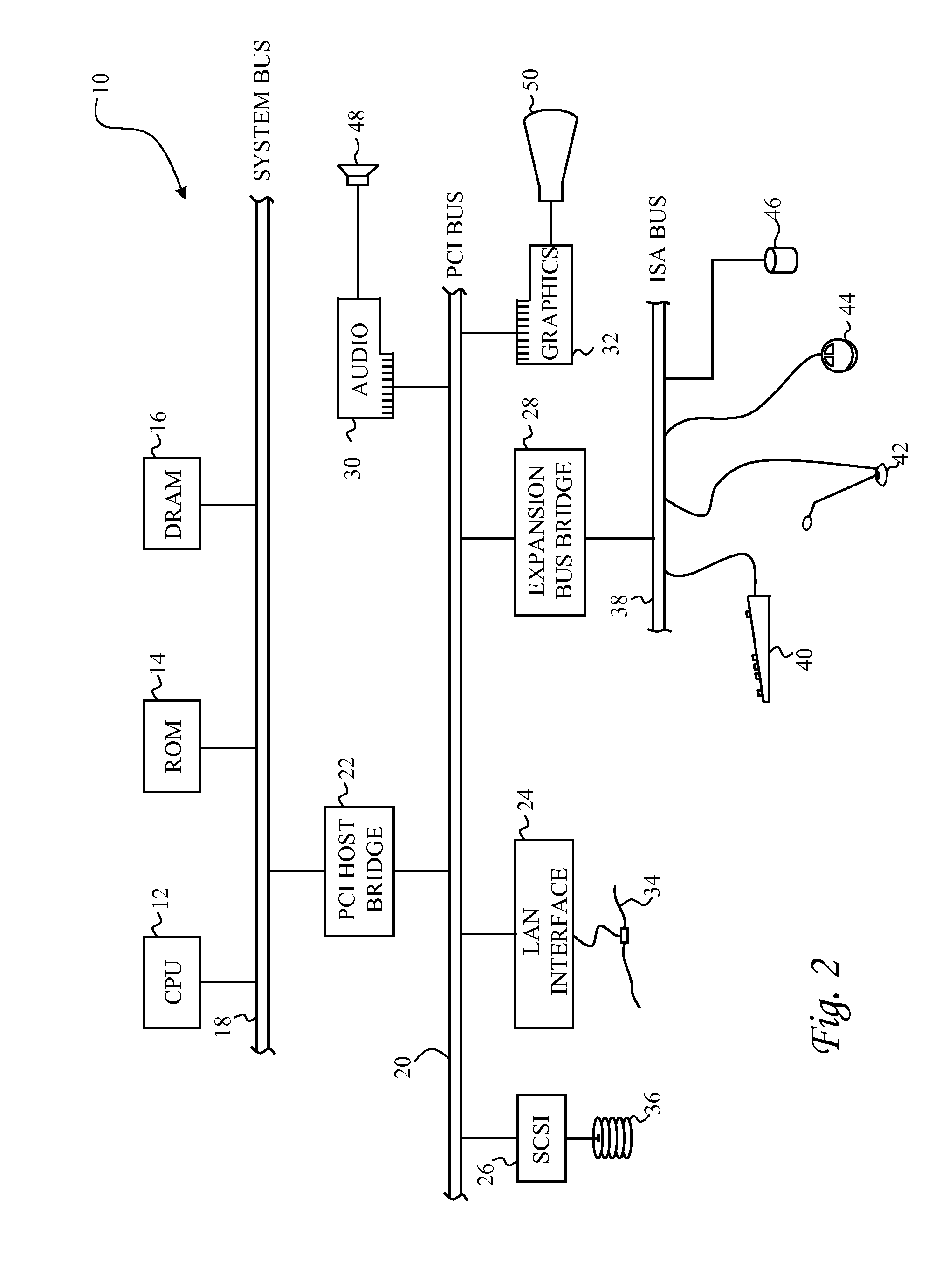
[0027] With reference now to the figures, and in particular with reference to FIG. 2, there is depicted one embodiment 10 of a computer system programmed to carry out computer-aided design of an integrated circuit in accordance with one implementation of the present invention. System 10 includes a central processing unit (CPU) 12 which carries out program instructions, firmware or read-only memory (ROM) 14 which stores the system's basic input / output logic, and a dynamic random access memory (DRAM) 16 which temporarily stores program instructions and operand data used by CPU 12. CPU 12, ROM 14 and DRAM 16 are all connected to a system bus 18. There may be additional structures in the memory hierarchy which are not depicted, such as on-board (L1) and second-level (L2) caches. In high performance implementations, system 10 may include multiple CPUs and a distributed system memory.

[0028] CPU 12, ROM 14 and DRAM 16 are also coupled to a peripheral component interconnect (PCI) local bu...


PUM


Abstract

A method of determining buffer insertion locations in an integrated circuit design establishes candidate locations for inserting buffers into a net, and selects buffer insertion locations from among the candidates based on slew constraints. The selection of buffer insertion locations preferably optimizes slack and buffer cost while keeping slew from any buffered node to any sink less than a required slew rate. The slew analysis computes an output slew SL(v) of a given buffer b inserted at a node v as SL(v)=RS(b)·C(v)+KS(b), where C(v) is the downstream capacitance at v, RS(b) is the slew resistance of buffer b, and KS(b) is the intrinsic slew of buffer b. The delay through a given buffer may also be computed based on signal polarity. However, the invention still preferably uses worst-case slew resistance and intrinsic slew in considering the slew constraints. If the selection of the buffer insertion locations results in no locations being selected due to slew violations, the present invention may advantageously find a partial solution by relaxing the slew constraint.

Description

CROSS-REFERENCE TO RELATED APPLICATION [0001] The present application is a continuation of copending U.S. patent application Ser. No. 10 / 996,292, and is related to U.S. Pat. No. 6,868,533 and U.S. Pat. No. 7,137,081, each of which is hereby incorporated.BACKGROUND OF THE INVENTION [0002] 1. Field of the Invention [0003] The present invention generally relates to the fabrication and design of semiconductor chips and integrated circuits, more specifically to a method of performing buffer insertion to manage timing and electrical requirements in an integrated circuit design. [0004] 2. Description of the Related Art [0005] Integrated circuits are used for a wide variety of electronic applications, from simple devices such as wristwatches, to the most complex computer systems. A microelectronic integrated circuit (IC) chip can generally be thought of as a collection of logic cells with electrical interconnections between the cells, formed on a semiconductor substrate (e.g., silicon). An ...

Claims


Application Information

Patent Timeline
Patent Type & Authority Applications(United States)
IPC IPC(8): G06F17/50
CPCG06F17/5068G06F17/5036G06F30/367G06F30/39
Inventor ALPERT, CHARLES JAYLI, ZHUOQUAY, STEPHEN THOMAS
Owner GLOBALFOUNDRIES INC
Learn More