
Near-field exposure mask, near-field exposure apparatus, and near-field exposure method

a technology of near-field exposure and exposure apparatus, which is applied in the direction of photo-taking processes, printers, instruments, etc., can solve the problems of increasing the size of the exposure apparatus, the cost of the corresponding resist, the cost of the apparatus, etc., and achieves the effect of simple mechanism

Inactive Publication Date: 2008-04-03
CANON KK
View PDF21 Cites 9 Cited by
  • Summary
  • Abstract
  • Description
  • Claims
  • Application Information

AI Technical Summary

Benefits of technology

[0018]A principal object of the present invention is to provide a near-field exposure mask capable of ensuring intimate contact thereof with an object to be exposed in a large area by a simple mechanism even in the case of the presence of waving on the object to be exposed.
[0033]In the near-field exposure mask according to the present invention, the mask base material comprises a synthetic resin material which is transparent to the exposure light and has a Young's modulus in a range of 1 GPa or more and 10 GPa or less. When the near-field exposure mask is used, it is possible to ensure intimate contact of the mask with the object to be exposed in a large area with a simple mechanism even in the case of the presence of waving on the object to be exposed.

Problems solved by technology

As described above, finer photolithography is advanced but with the shortened wavelength of light, there arise many problems regarding an increase in size of an exposure apparatus, development of a lens in the wavelength range, apparatus cost, cost of a corresponding resist, etc.
In such a method, however, fine processing is performed by a single processing probe (or plural processing probes) according to vector scanning in a single stroke manner, so that a throughput is not sufficiently improved.
However, it is difficult to bring the mask using a rigid material such as the quartz glass as the mask base material into contact with the substrate to be exposed at an entire surface having a large area when the presence of waving on the exposure mask and the substrate to be exposed is taken into consideration.
However, this method requires a production process comprising many steps for producing a mask having a thin film structure and involves a possibility of breakage at a thin portion of the mask during application or release of the pressure.

Method used


Image

  • Near-field exposure mask, near-field exposure apparatus, and near-field exposure method
  • Near-field exposure mask, near-field exposure apparatus, and near-field exposure method
  • Near-field exposure mask, near-field exposure apparatus, and near-field exposure method

Examples


embodiment 1

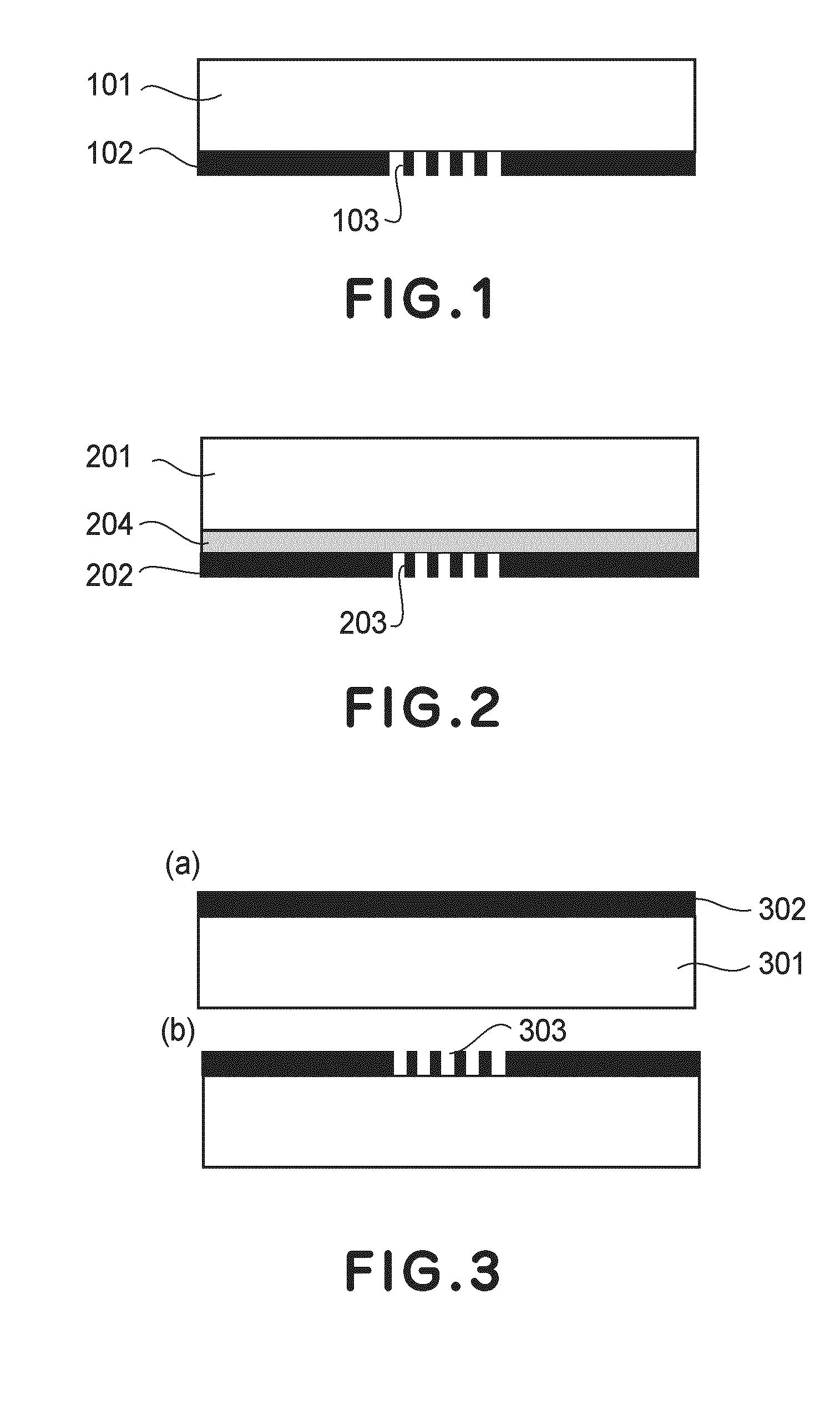
[0070]A production process of a near-field exposure mask and the near-field exposure mask produced through the production process will be described.

[0071]FIGS. 3(a) and 3(b) are schematic views for illustrating the production process of the near-field exposure mask in this embodiment.

[0072]In this embodiment, first, on a mask base material 301, a light blocking film 302 is formed in a film by using a synthetic resin material which is transparent to exposure light and has a Young's modulus in a range of 1 GPa or more and 10 GPa or less as described in the above mentioned embodiment (FIG. 3(a)). The film formation is performed by sputtering, electron beam deposition, resistance heating deposition, chemical vapor deposition, or the like.

[0073]Then, a minute (fine) pattern 303 is formed with respect to the light blocking film 302 (FIG. 3(B)).

[0074]The patterning of the pattern 303 is performed by etching using, as a mask, a resist subjected to direct processing using a focused ion beam ...

embodiment 2

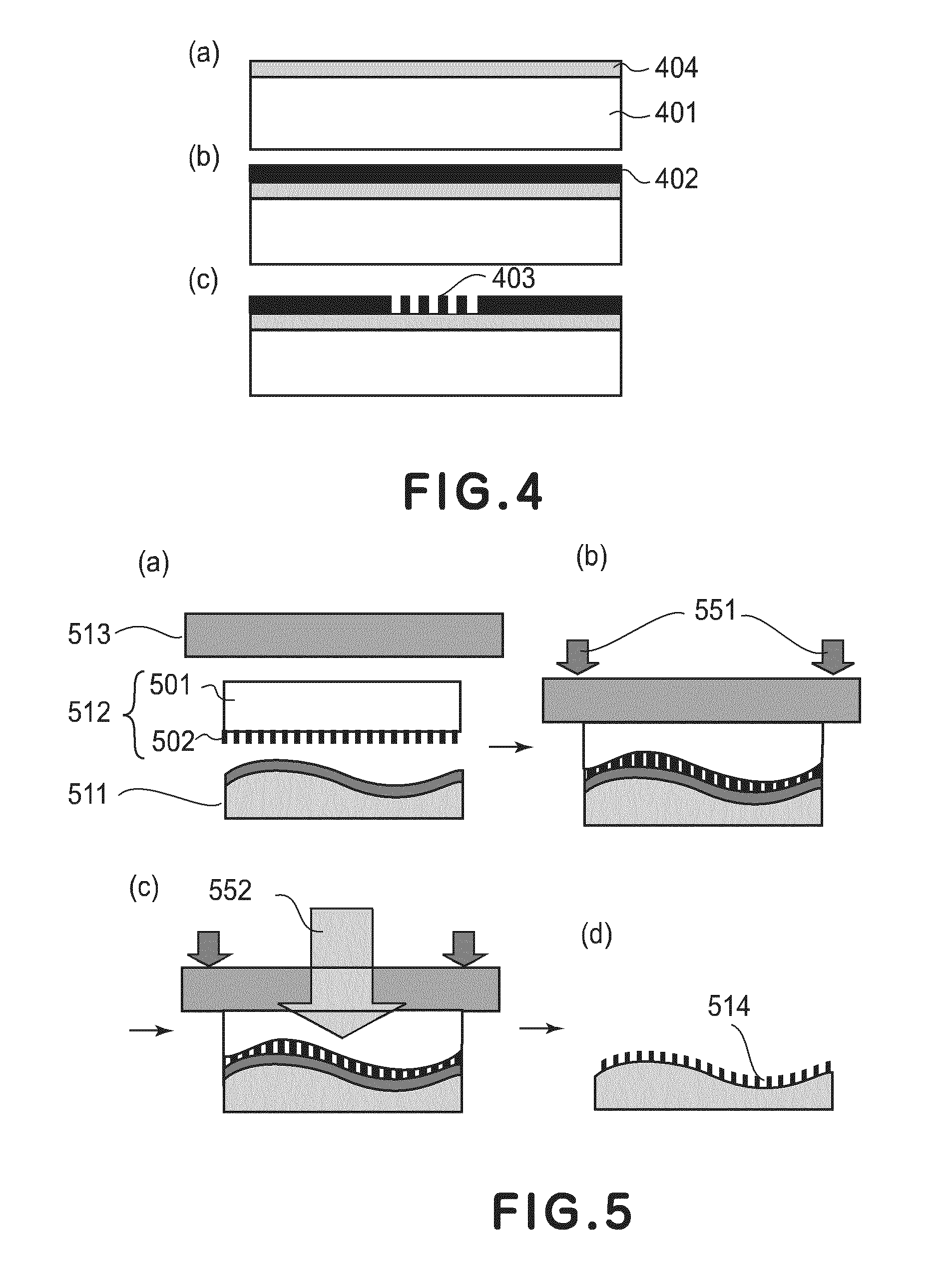
[0082]A production process of a near-field exposure mask including an intermediate layer and the near-field exposure mask produced through the production process will be described.

[0083]FIGS. 4(a), 4(b) and 4(c) are schematic views for illustrating the production process of the near-field exposure mask including the intermediate layer.

[0084]A mask base material 401, film formation of a light blocking film 402, and formation of a minute pattern 403 are similar to those in Embodiment 1, so that description thereof will be omitted.

[0085]In this embodiment, on the mask base material 401, an intermediate layer 404 is formed in a film (FIG. 4(a)).

[0086]In the case where SiO2 or SiN is employed as a material for the intermediate layer, the film formation is performed by sputtering, electron beam deposition, resistance heating deposition, chemical vapor deposition, or the like.

[0087]In the case where spin-on glass is used as the material for the intermediate layer, the film formation is per...

embodiment 3

[0089]A near-field exposure method using a near-field exposure mask according to the present invention will be described.

[0090]FIGS. 5(a) to 5(d) are schematic views for illustrating the near-field exposure method of this embodiment.

[0091]On a mask base material 501 side of a near-field exposure mask 512, a quartz glass 513 as a rigid member transparent to exposure light is provided and on a light blocking film 502 side of the near-field exposure mask 512, a resist-coated substrate to be exposed 511 is provided (FIG. 5(a)). The transparent rigid member is, however, not limited to the quartz glass 513. In this embodiment, the quartz glass 513 functions as an exposure mask supporting mechanism.

[0092]The resist is usable in this embodiment irrespective of the type thereof such as a positive type or a negative type so long as the resist has photosensitivity with respect to light from a light source. Examples of the positive resist may include diazonaphthoquinone-novolac resist and a che...


PUM

PropertyMeasurementUnit
Young's modulusaaaaaaaaaa
wavelengthaaaaaaaaaa
Young's modulusaaaaaaaaaa

Abstract

A near-field exposure mask includes a light blocking film having an opening smaller than a wavelength of exposure light, and a mask base material for holding the light blocking film. The near-field exposure mask is configured and positioned to effect exposure of an object to be exposed to near-field light generated corresponding to the opening during contact thereof with the object to be exposed. The mask base material is transparent to the exposure light and comprises a synthetic resin material having Young's modulus in a range of 1 GPa or more to 10 GPa or less.

Description

FIELD OF THE INVENTION AND RELATED ART[0001]The present invention relates to a near-field exposure mask, a near-field exposure apparatus including the near-field exposure mask, and a near-field exposure method using the near-field exposure mask.[0002]With progresses of an increase in capacity of a semiconductor memory and speedup and high integration of a central processing unit (CPU), further fine photolithography is indispensable.[0003]Generally, the limit of fine processing in a photolithographic apparatus is about ⅓ of a wavelength of light used.[0004]For this reason, the wavelength of light used for the photolithographic apparatus is further shortened, so that it is possible to effect fine processing on the order of about 50 nm.[0005]As described above, finer photolithography is advanced but with the shortened wavelength of light, there arise many problems regarding an increase in size of an exposure apparatus, development of a lens in the wavelength range, apparatus cost, cost...

Claims


Application Information

Patent Timeline
Patent Type & Authority Applications(United States)
IPC IPC(8): G03F1/00G03B27/58G03B27/60
CPCB82Y10/00G03F1/14G03F7/7035G03F7/2014G03F7/24G03F1/60G03F1/50
Inventor ITO, TOSHIKIMIZUTANI, NATSUHIKO
Owner CANON KK
Learn More