Mode selection and switching logic in a closed-loop pulse width modulation valve-based transmission control system

a transmission control system and pulse width modulation technology, applied in fluid pressure control, process and machine control, instruments, etc., can solve the problems of inability to recalibrate or apply corrections to pre-programmed solenoid valve control systems while in operation, failure to take advantage of feedback information that could be provided to any sensors, and less accura

Inactive Publication Date: 2008-04-03
EATON CORP
View PDF38 Cites 24 Cited by
  • Summary
  • Abstract
  • Description
  • Claims
  • Application Information

AI Technical Summary

Benefits of technology

[0019]One embodiment provides a method for re-calibrating the control pressure Pc versus the duty cycle (Pc vs. DC). The re-calibrated Pc vs. DC is used to update the feedba

Problems solved by technology

However, pre-programmed solenoid valve control systems are not able to re-calibrate, or apply corrections to, their pre-programmed rules while in operation.
Such solenoid valve control systems may be characterized as “open loop” because they provide input to a solenoid valve, but fail to take advantage of feedback information that could be provided any sensors that measure solenoid valve output.
Even if the calibration is initially accurate, over time it becomes less accurate due to the wear of parts, degradation of hydraulic

Method used


Image

  • Mode selection and switching logic in a closed-loop pulse width modulation valve-based transmission control system
  • Mode selection and switching logic in a closed-loop pulse width modulation valve-based transmission control system
  • Mode selection and switching logic in a closed-loop pulse width modulation valve-based transmission control system

Examples


example logic 1

IF (Fluid Temperature>Threshold Temperature), THEN (Use Controller A 304A); and

IF (Fluid Temperature≦Threshold Temperature), THEN (Use Controller B 304B).

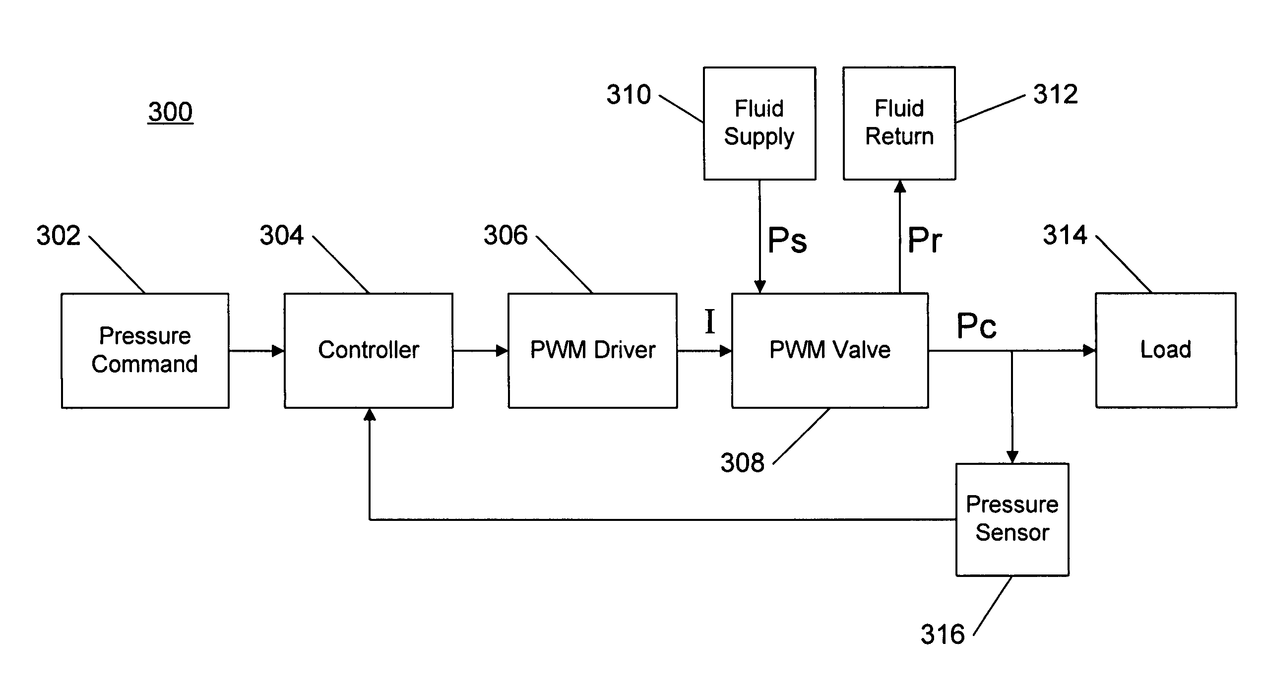
[0067]In another embodiment, the switching logic processor 602 determines whether the controller A 304A or the controller B 305B provides output to the PWM driver 306. This determination is based on a signal provided by the external inputs element 502 that is representative of other operating conditions of the feedback control system 600. If the feedback control system 600 is part of an automatic transmission control system, for example, information regarding a current gear number (which may affect the properties of the load 314) may be received from the external inputs element 502, and used to determine which controller is selected (i.e., controller A 304A or controller B 304B).

[0068]The switching logic processor 602 may use a combination of inputs to determine which controller is used, as shown by EXAMPLE LOGIC 2 as set forth bel...

example logic 2

IF (Fluid Temperature>Threshold AND Current Gear Number>Selected Gear Number), THEN (Use Controller A 304A); and

IF (Fluid TemperatureSelected Gear Number), THEN (Use Controller B 304B).

[0069]In another embodiment, a pressure signal output by the pressure sensor 316 may be used by the switching logic processor 602 to determine whether the controller A 304A or the controller B 305B is used to provide output to the PWM driver 306. For example, for a selected range of values of the pressure signal, the controller A 304A may be used, and for another selected range of values of the pressure signal, the controller B 304 B may be used.

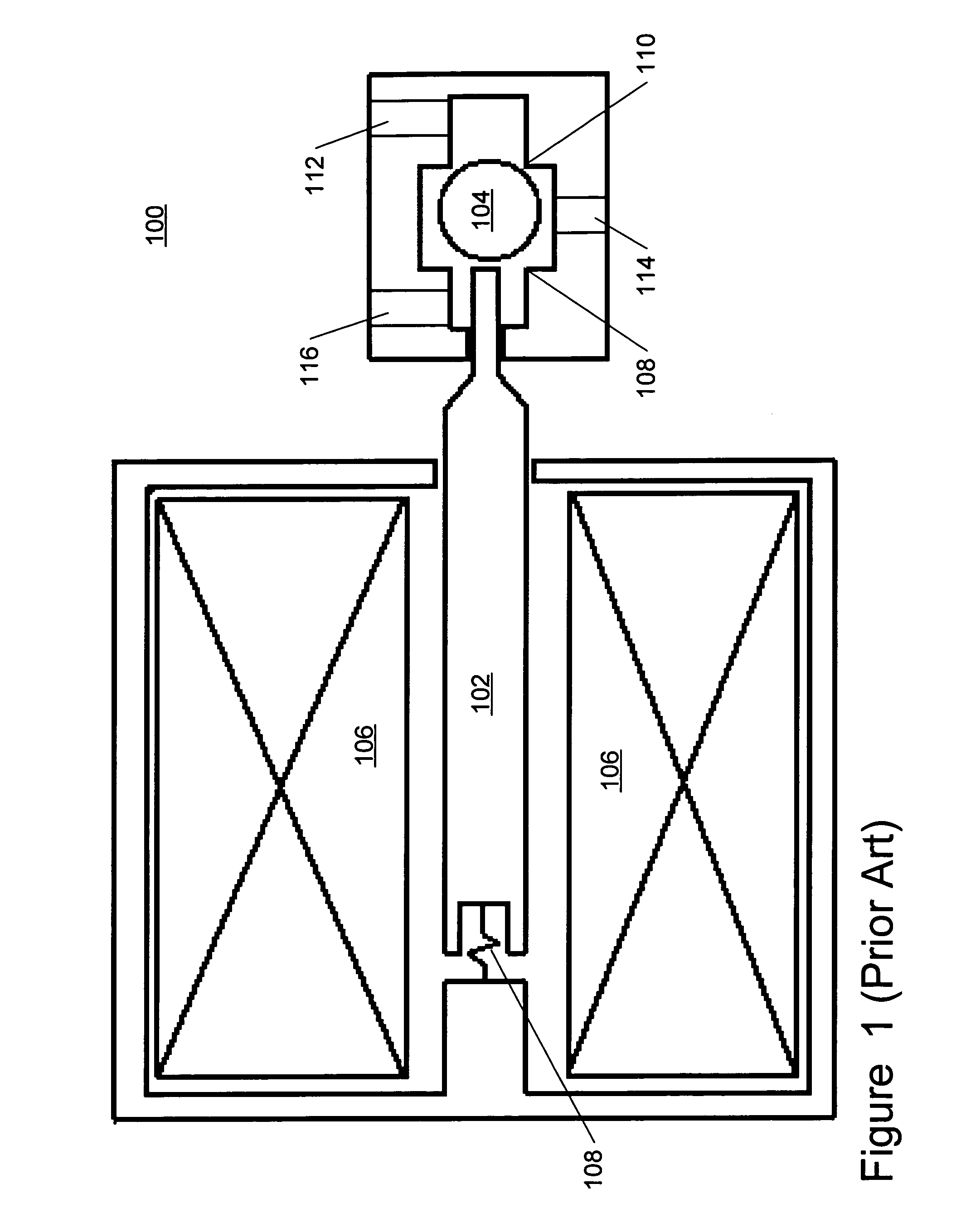
[0070]In yet another embodiment, the switching logic processor 602 determines whether the controller A 304A or the controller B 304B is used to provide output to the PWM driver 306 based on a current flowing in the coil 106 (FIG. 1) as represented by a signal received from the sensor A 604. Because the current in the coil 106 is a combination of the drive curr...


PUM


Abstract

A pulse width modulated (PWM) valve-based hydraulic control system is disclosed. In one embodiment, a feedback control system includes a controller that receives a pressure command signal and a pressure feedback signal. The controller generates a duty cycle control signal that controls a PWM valve. The PWM valve provides a control pressure Pc to control a load, such as an actuator of an automatic transmission system. A pressure sensor measures the control pressure Pc and provides the pressure feedback signal. In another embodiment, a compensator provides compensation for linear and nonlinear effects in the pressure feedback signal, based at least in part, on other inputs, such as fluid temperature. In other embodiments, a plurality of controllers are provided, and a controller is selected by a switching logic processor, or by phase-in and phase-out filters, based on the pressure feedback signal and other inputs. A re-calibration process for the Pc versus duty cycle response of the PWM valve is also disclosed. The re-calibration method updates the feedback control system processes to maintain performance despite variations due to wear, temperature, and other factors.

Description

CROSS REFERENCE TO RELATED APPLICATION AND PATENT[0001]This application is related to the pending U.S. patent application Ser. No. 10 / 874,133, filed Jun. 22, 2004, titled “CLOSED-LOOP VALVE-BASED TRANSMISSION CONTROL ALGORITHM”; and to U.S. Pat. No. 6,807,472, issued Oct. 19, 2004, titled “CLOSED LOOP CONTROL OF SHIFTING CLUTCH ACTUATORS IN AN AUTOMATIC SPEED CHANGE TRANSMISSION.” This pending patent application and issued patent are commonly owned by the assignee hereof, and are hereby fully incorporated by reference herein as though set forth in full, for teachings on closed-loop hydraulic control systems.BACKGROUND[0002]1. Field[0003]The present disclosure relates in general to electronically controlled hydraulic (electro-hydraulic) systems using solenoid operated valves, and more particularly to closed-loop control of electro-hydraulic systems using pulse width modulation (PWM) valves.[0004]2. Description of Related Art[0005]Solenoid operated hydraulic valves (referred to herein...

Claims


Application Information

Patent Timeline
IPC IPC(8): G06F19/00
CPCF16H61/0251F16H2061/0255Y10T477/60G05D16/2013F16H2342/10
Inventor DELL'EVA, MARK L.SURIANARAYANAN, ANANTHAKRISHNANHERBERT, DAVID E.
Owner EATON CORP
Why Eureka
Try Eureka