Counter-Rotating Integrated Propeller Assembly

a propeller assembly and counter-rotating technology, applied in the field of marine propulsion systems, can solve the problems of high cost, complexity, weight and cost, and the need to purchase transmission and propulsion systems, and achieve the effect of optimizing the effect of upstream and downstream slipstream velocities, saving substantial cost and size, and reliable operation

Inactive Publication Date: 2008-04-17
SINREICH MARK G
View PDF4 Cites 29 Cited by
  • Summary
  • Abstract
  • Description
  • Claims
  • Application Information

AI Technical Summary

Benefits of technology

[0013]Another advantage of the present invention is that neither of the propellers is directly coupled to the drive shaft, nor does any propeller rotate at the speed of the drive shaft. This allows the propeller assembly to be installed on drive shafts connected to high speed propulsion systems. Instead of being directly connected to the drive shaft, each propeller spins freely on bearings riding on and solely supported by the drive shaft. The propeller assembly includes appropriate gearing, so that both propellers turn at optimal reduced speed with respect to the drive shaft. The speed reduction of the motor drive shaft to match optimal propeller speed is performed by gear reduction internal to the propeller hubs, offering a wide range of gear ratios. The gear reduction also provides different speed ratios for each propeller, optimizing the effects of upstream and downstream slipstream velocities, and allowing further optimization of propeller diameter, pitch, and blade shape.
[0014]In accordance with the present invention, the speed reduction is accomplished by gears that are optimally integrated into the hubs of the propellers and supported entirely on the drive shaft, resulting in a compact design that avoids the necessity of in-line transmissions, gear boxes, support struts or other vessel mounted structures, saving substantially on cost and size. The gears are preferably a planetary gear set, providing reliable operation, which is compact and can be completely contained within the propeller hub. However, other gear configurations that accomplish the same results can be used. Further, a simple single stage gear reduction can be used, or compound gearing can be used, or multiple-stage gearing can be used, to gain higher or lower gear reduction ratios.
[0015]The propeller assembly of this invention can be lubricated entirely by means of the water in which the propeller assembly operates. To provide water lubrication, the entire assembly is exposed to water, avoiding the need for complex seals or gaskets to retain lubricating oil, and the problems of sealing failures and leaking of lubricating oil which would seep into the environment. Studies have reported that leaks from marine propulsion drive unit oil and lubrication systems pollute the environment with immense quantities of petroleum products every year. Since the assembly can be water lubricated, it is feasible and may even be optimal, to fabricate many of the components of the propeller assembly, such as gears and bearings, of composite materials when the propeller assembly is used with the power levels required by small craft and yachts. To achieve higher power output levels, this invention can utilize oil lubrication as well.
[0016]The propeller assembly of the present invention is versatile and can be used in a variety of applications. It can be used with a dual shaft electric motor, with a dual propeller assembly installed on both the forward facing and the aft facing motor shafts, one being in a puller mode, the other being a pusher mode, resulting in a further increase in efficiency. It can be used with ducted propellers, wherein a circumferential duct around each propeller is advantageously used to increase propeller efficiency and total thrust, especially at lower speeds where slower rotating propellers can be most effective. It can be adapted to power levels ranging from 1 HP to 1,000 HP or more, with modifications of materials and gear geometries.
[0017]The principals of the present invention can be modified for various specific applications. Modified versions can be created to provide upgrades in the outboard motor market where owners want notably increased thrust and power levels at lower speeds. Modified versions can also be created to provide upgrades to inboard drive shaft applications where owners desire notably increased thrust, power levels, top speed, power out of the hole, and above all fuel efficiency. Further modifications can be made to maximize the potential of the nascent market for hybrid and electric propulsion.
[0018]These and other advantages are provided by the present invention of a multiple counter-rotating propeller assembly, which comprises a drive shaft, a first propeller and a second propeller. The first propeller comprises a first hub which is supported on the drive shaft and which is freely rotatable with respect to the drive shaft, a plurality of first blades mounted on the hub, and a gear set connected to the drive shaft and to the hub, the gear set rotating the hub in a direction opposite to the direction of rotation of the drive shaft. The second propeller comprises a second hub which is supported on the drive shaft and which is freely rotatable with respect to the drive shaft, and a plurality of second blades mounted on the second hub, the second hub connected to the gear set in the first hub to rotate the second hub in the same direction as the rotation of the drive shaft.

Problems solved by technology

Dual propellers also offset torque imbalance which result from the use of a single propeller.
While these systems have their advantages, they also have had many important disadvantages, particularly their complexity, weight and cost.
The prior art counter-rotating propeller systems usually required a complex gear box, often with precision cut steel gears, inside the vessel.
Highly specialized and expensive engines, transmissions and propulsion systems had to be purchased to utilize the advantages of the counter-rotating propeller feature.
Because of their complexity, an oil-filled transmission was often required, which could leak oil and create an environmental problem.
As a result, these prior art systems generally have not been suitable for many applications, particularly for small craft and smaller yachts.
Hybrid propulsion systems, which utilize diesel generators that power electric motors, have found broad acceptance in large ships, but they have not been feasible in smaller craft for technical or economic reasons.
While great advances have been made in highly reliable, permanent magnet brushless direct-current (BLDC) motors and other electric motor technologies that have great promise for hybrid propulsion, attempts to apply them to small craft have found limited success.
The application of hybrid propulsion to small craft has been hampered in part by the fundamental mismatch between optimal propeller speed and optimal motor speed.
Prior efforts to create a BLDC motor that runs at slower propeller speeds have resulted in motors that are many times larger and heavier than they otherwise need to be.
A large motor with large surface area is also needed to dissipate the heat loss generated by the motor into the surrounding air, and a large motor needs to be placed inside the hull, requiring an engine room, motor mounts, stern shaft, stern tube, bearings, seals, shaft supports, the risk of water leaks and all of the heavy and expensive structure that current diesel engines require.
Attempts to use forced water cooling for the heat removal in BLDC motors have added complexity, cost, weight and the risk of water intrusion and sinking.
Forced water cooling does not eliminate the need for the interior space, stern shaft, weight and cost of a traditional marine propulsion system.
Attempts to solve many of these problems by putting the electric motor in a pod in the water outside the vessel have been successful in very large commercial vessels such as cruise ships, but have not found success in smaller vessels, due to the mismatch between the optimal motor speed and optimal propeller speed.
To run such a smaller motor at low enough speeds to directly drive a propeller further wasted a majority of the power potential of the motor.
Another prior attempt at solving the problem was to squeeze a gear reduction package onto the end of the motor in the pod, but this required an oil-filled integrated gear box, with complex seals to prevent leaks of oil into the environment.
This complex solution has not scaled to smaller craft which have efficiency requirements and cost limitations.

Method used


Image

  • Counter-Rotating Integrated Propeller Assembly
  • Counter-Rotating Integrated Propeller Assembly
  • Counter-Rotating Integrated Propeller Assembly

Examples


Embodiment Construction

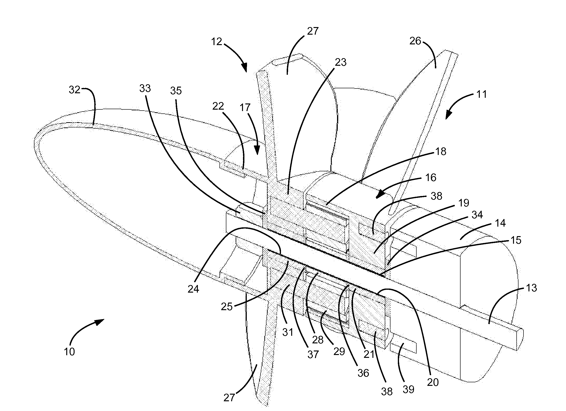
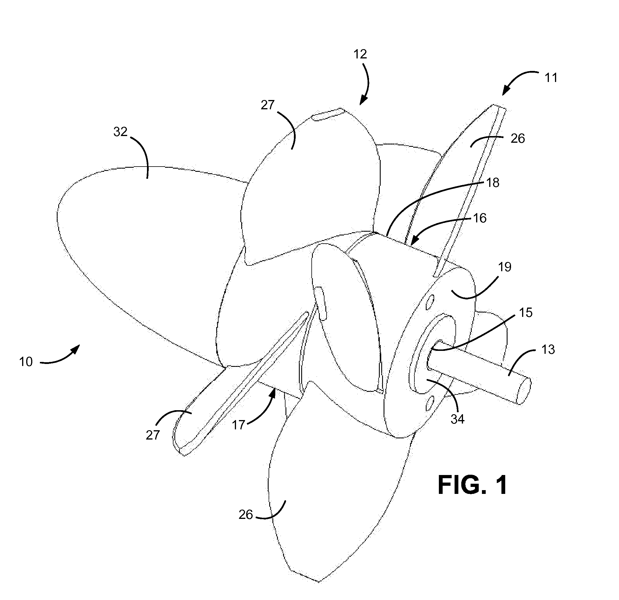
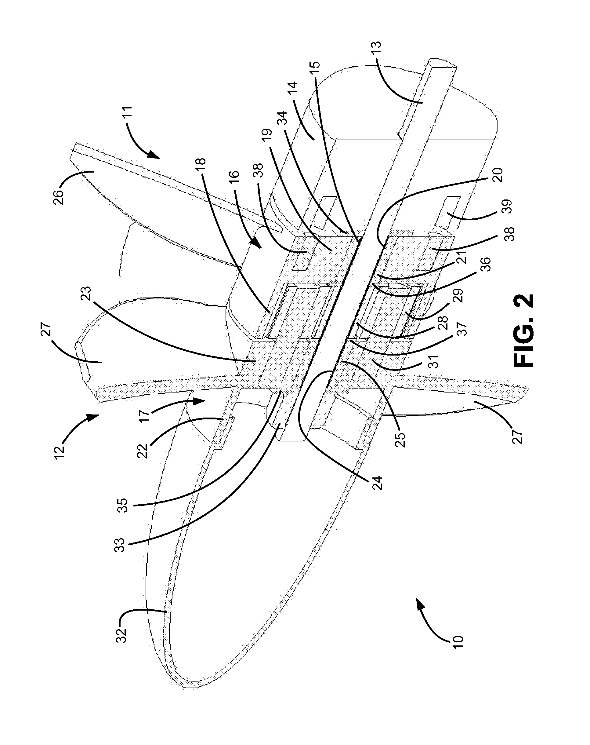
[0025]Referring more particularly to the drawings, and initially to FIG. 1, there is shown a propeller assembly 10 according the present invention, comprising a first propeller set 11 and a second propeller set 12. The assembly 10 is mounted on the end of a drive shaft 13 (FIGS. 2 and 3) which extends from a marine vessel or motor housing 14. The drive shaft 13 which is connected to a suitable propulsion system such as an electric motor, may be hollow or solid. The drive shaft 13 extends through a hollow mounting tube 15 which is locked on the draft shaft and rotates with the drive shaft. The hollow mounting tube 15 is provided only as a convenience allowing the dual propeller system to be assembled prior to its installation on the drive shaft 13. It is also contemplated that the components of the assembly, including gearing, bearings, hubs and propellers, can be directly mounted to the drive shaft 13. Each of the propeller sets 11 and 12 has a hollow cylindrical hub 16 and 17, resp...


PUM


Abstract

A multiple counter-rotating propeller assembly includes a drive shaft, a first propeller and a second propeller. The first propeller has a first hub which is supported on the drive shaft and which is freely rotatable with respect to the drive shaft, a plurality of first blades mounted on the hub, and a gear set connected to the drive shaft and to the hub, the gear set rotating the hub in a direction opposite to the direction of rotation of the drive shaft. The second propeller has a second hub which is supported on the drive shaft and which is freely rotatable with respect to the drive shaft, and a plurality of second blades mounted on the second hub, the second hub connected to the gear set in the first hub to rotate the second hub in the same direction as the rotation of the drive shaft. The entire propeller assembly is supported solely on the drive shaft, and the inclusion of the gear set which provides all of the gear reduction completely within the propeller hub provides a compact design.

Description

FIELD OF INVENTION[0001]The present invention relates to marine propulsion systems comprising dual counter-rotating propellers, and more particularly, to transmission of power from a drive shaft to the propellers.BACKGROUND OF THE INVENTION[0002]Marine propulsion systems that include counter-rotating propellers are well known. Among the advantages of these systems is their efficiency, particularly at high speeds and high thrusts, resulting in lower fuel costs. When two propellers are used, it is also possible to reduce the diameters of the propellers, which can provide a more compact design. Dual propellers also offset torque imbalance which result from the use of a single propeller.[0003]Examples of counter-rotating propeller marine propulsion systems are shown in U.S. Pat. No. 2,543,453, issued to Fuller; U.S. Pat. No. 3,087,553, issued to Kostyun; U.S. Pat. No. 4,074,652, issued to Jackson; U.S. Pat. No. 4,360,348, issued to DeMarco;: U.S. Pat. No. 4,540,369, issued to Caires; U....

Claims


Application Information

Patent Timeline
Patent Type & Authority Applications(United States)
IPC IPC(8): B64C11/48
CPCB63H5/10
Inventor SINREICH, MARK G.
Owner SINREICH MARK G
Why Eureka
Try Eureka